The NEC2 simulation program contains approximations and the results obtained from the computer simulation will deviate slightly from the true performance in the real world.
The results from the NEC2 simulations depend on the number of segments for each wire. The differences are not large but they correspond to an uncertainty in element lengths that will add to uncertainties due to manufacturing tolerances in element diameters, lengths and positions on the boom tube.
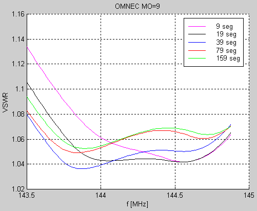
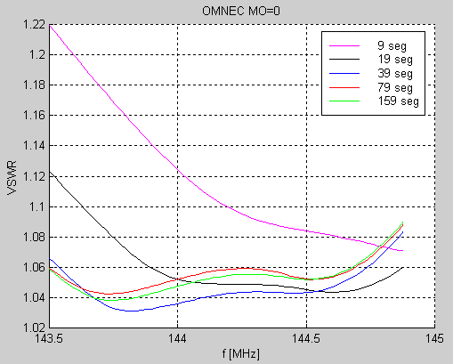
Figure 1 shows the simulated impedance vs frequency for 2SA13 with 9, 19, 39, 79 and 159 segments on each element when the option MO=1 of OMNEC is used. Figure 2 shows the same thing for MO=0, the original NEC2 program.

Figure 1 OMNEC modified NEC2 simulations of impedance vs frequency for 2SA13. |
|
The data files used to produce figure 1 are here: SEG09_RES_MO9.NEC SEG19_RES_MO9.NEC SEG39_RES_MO9.NEC SEG79_RES_MO9.NEC SEG159_RES_MO9.NEC |

Figure 2 NEC2 simulations of impedance vs frequency for 2SA13. |
|
The data files used to produce figure 2 are here: SEG09_RES_MO0.NEC SEG19_RES_MO0.NEC SEG39_RES_MO0.NEC SEG79_RES_MO0.NEC SEG159_RES_MO0.NEC The frequency at which the imaginary part of the impedance goes through zero increases by 50 kHz each time the number of segments is doubled when the option MO=1 is used. With MO=0 (the original NEC2 software) the result does not differ much between simulations with 39, 79 or 159 segmens while a simulation with only 9 segments on each element differs by nearly 500 kHz. It is not easy to judge the abolute accuracy from these simulations. The MO=1 option has limited accuracy, it was designed to allow fast optimisation with few segments but the accuracy is limited. At the time this option was developed, the maximum number of segments the computer could handle was below 40 because of memory restrictions running FORTRAN under MSDOS. In all, the above indicates an uncertainty in the order of 100 kHz. It is a little too much to be neglected in a design like the 2SA13, therefore one reference antenna was manufactured and the dimensions were carefully measured. The impedance of this reference antenna was then measured in 401 points from 134 to 154 MHz to allow a calibration of the simulations. The impedance of an antenna is of course affected by the surroundings and therefore six measurements were made at different positions of the antenna as listed in table 3. The impedance vs frequency curves of these measurements are shown in figure 3. |
Table 1. Position of reference antenna above ground for impedance measurements. The data files contain the complex reflection coefficients. |
|
|

Figure 3 Measured impedance of reference antenna at different heights above ground. |
|
When the antenna points into the sky, the back lobe points into the ground. The radiation leaving the antenna through the back lobe gets reflected on the ground and is picked up again by the back lobe and adds to the power reflected by the antenna thereby changing the impedance. It is not surprising at all that the impedance varies with height for an antenna that points into the sky. The black curve which is at 0.96 meters above ground deviates significantly from the other measurementsas one might expect. The remaining measurements agree within +/- 1 ohm inside the design passband 144.0 - 144.4 MHz. At 145 MHz where the front to back ratio is poor, the measurements differ about ten times more. The dimensions of the reference antenna were measured at a temperature of 18-20oC. The impedances were measured at 6oC. The element lengths were corrected with the known thermal expansion coefficient of aluminium while the boom length was measured with a laser instrument both at room temperature and at 6oC and the positions of all elements were corrected accordingly. Figure 4 shows the best measurement FILE04.F1 and OMNEC simulations with 39 segments. Figure 4 also shows the result of a NEC4 simulation with 39 segments. The geometry of the reference antenna at 6oC in NEC2 format 2SA13_REF.NEC was used as the input to the simulations. |

Figure 4 Measured impedance (blue) compared to NEC2, NEC4 and modified NEC2 simulations. All simulations use 39 segments on each element. |
|
As one might expect, the modified NEC2 simulation gives the correct resonance frequency - the modification has been calibrated against real antennas. It is interesting to note that NEC4 deviates more than NEC2. At first this is unexpected, but a possible explanation will be given below. All simulations give a maximum impedance of about 175 ohms while the measurements give about 225 ohms. To evaluate what the different resonance frequencies mean in terms of element lengths, the real world physical dimensions were changed by adding two corrections to the elements. One for the 6 mm solid rod elements and a different correction for the 10/8 mm tube elements. The corrections were least squares fitted the simulations to become equal to the measurements. An arbitrary impedance error was included in the least squares fit. All six measurements were fitted independently to modified NEC2, original NEC 2 and NEC4. For each model 19 and 39 segments were used. The corrections to the element lengths and to the impedance that makes each simulation fit each experimental curve are listed in tables 3 to 6 and the associated RMS error on the impedances are listed in table 2. |
Table 2.Root mean square error of impedances calculated for 140 frequencies in the interval 134 to 154 MHz when the model is corrected with four corrections. Length of 6mm rod, length of 10/8 mm tube, real and imaginary perts of the impedance. |
|
With RMS errors of about 2 ohms, the experimental and theoretical impedance curves have to look very similar. Figure 5 shows the fit of FILE04 to modified NEC2 with 19 segments and figure 6 shows FILE04 fitted to NEC4 with 39 segments. |

Figure 5 Modified NEC2 with 19 segments per element fitted to the measured impedance data in FILE04. |
|
|

Figure 6 NEC4 with 39 segments per element fitted to the measured impedance data in FILE04. |
|
The deviations between model and experiment in figures 4 and 5 are well within the experimental accuracy as is the fit to the other data files except for FILE00 in which the ground reflections are too strong due to the short distance to ground. The corrections needed for optimum fit which are listed in tables 3 to 6 allow some definite conclusions. First of all, the difference between the correction for the 6 mm rod and for the 10/8 mm tube is about 2.2 mm. This is shown in table 7 which is table 3 minus table 4. |
Table 3.Correction to solid 6 mm elements that make the different models fit to measured impedance values |
|
|
Table 4.Correction to 10/8 mm tube elements that make the different models fit to measured impedance values |
|
|
Table 5. Correction to the real part of the impedance that makes the different models fit to measured impedance values. |
|
|
Table 6. Correction to the imaginary part of the impedance that makes the different models fit to measured impedance values. |
|
|
Table 7.Difference between correction to rod lengths and to tube lengths. |
|
The data in FILE04 and FILE05 are with the antenna pointing at an elevation angle close to 60 degrees, but the height differs by a factor of two. The fact that these measurements are similar indicates that the antenna does not radiate much into its mirror image below the ground plane. The two files FILE01 and FILE02 differ by 0.25 wavelengths in height but both are high above ground. The phase of the reflected wave from the ground plane should therefore differ by 180 degrees so the impedance in free space should be close to the average of these two measurements. For NEC4 with 39 segments, the lengths of the 6 mm rods have to be increased by 0.7 mm while the 10 mm tubes have to be shortened by 1.5 mm to get agreement between the NEC4 simulation and the real world antenna in free space. We may interpret this like this: NEC2 and NEC4 need two corrections on the element lengths.
It is no longer surprising that NEC2 fits better than NEC4 when no correction is made. The two corrections have opposite sign. NEC2 is less accurate than NEC4 and the errors due to various approximations happen to cancel the correction that should have been included for using tubes rather than rods. Table 5 shows that a correction is not needed for the real part of the impedance. This is expected. Such an correction would be hard to explain. Table 6 shows that about 3 ohms of capacitive reactance has to be added in series at the feed point to bring the imaginary part of the feed point impedance in agreement with the simulations. This is expected and corresponds to a 3nH inductance in the real world that was not accounted for in the model. At the feed point, the coaxial cable is opened and run as a high impedance balanced line for a few mm and this means a series inductance which is not included in the model. Calibration was done with a coaxial cable of the same length which was connected to an N-connector. |