 Fig. 1. Transmitter off.
Setup to measure transmitter spectral purityThese measurements were made with Linrad running on a PentiumIII 600MHz computer with a modified Delta44 soundcard. The 144 MHz signals were converted to audio by use of the WSE converters RX144, RX70, RX10700 and RX2500.Linrad was run in Tx test mode Figure 1 shows the screen when the IC-706MKIIG is not transmitting. (It is in receive mode)
|
 Fig. 1. Transmitter off.
The measurement system has much better dynamic range than required for these measurements so no corrections have to be made for the noise contribution from the measurement system.
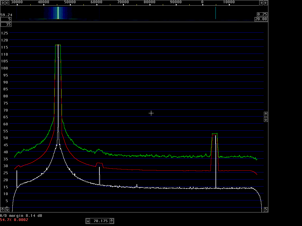 Fig. 2. Continous carrier from IC706-MKIIG at 14 MHz.
The numbers in table 1 are extracted from the red curve of figure 2 which is average power in 2.4 kHz bandwidth (100 dB is 475 pixels).
------------------------------------------------------
   Freq       Coordinates          Level    Sideband
separation     X        Y         2.4 kHz    noise
   (kHz)    (pixels) (pixels)      (dB)     (dBc/Hz)
     0        198      154          0.0        -
     5        243      526         78.3       112.3
    10        288      557         84.8       118.8
    20        378      573         88.2       122.2
    50        607      580         89.7       123.7
------------------------------------------------------
Table 1. Spectrum of IC706MKIIG emitting continuous carrier.
 Fig. 3. Morse code transmission from IC706-MKIIG at 14 MHz.
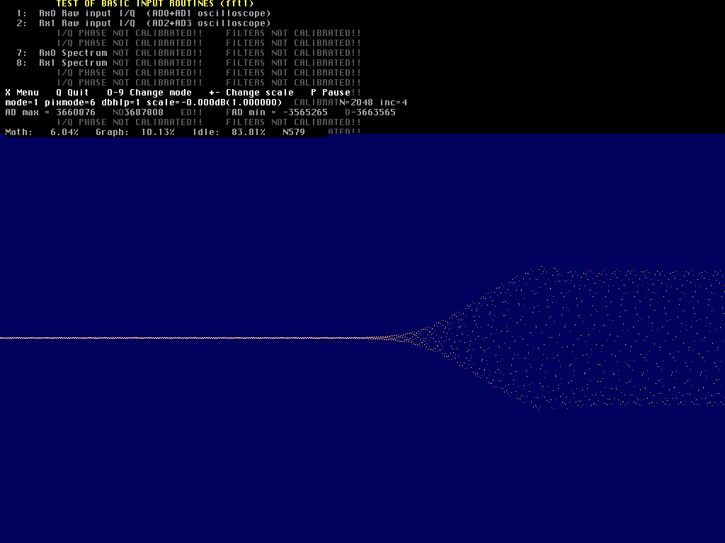 Fig. 4. Morse keying in the time domain.
It is pretty obvious that the ALC acts very fast - and too much. It is clear that the waveform is rising too fast and that the gain becomes reduced - and that there is an oscillation in the ALC circuit that causes AM modulation at about 5 kHz for a very short time. The same phenomenon is present in SSB mode but it is much less disturbing there. I do not know whether this unit is faulty or mis-adjusted or if it is an early model that had design errors that are corrected in later models. The serial number of this unit is 04668. Another IC706MKIIG with serial number 06034 that I have tested did not have this error.
The error is even worse when there is a long pause before the key is pressed. This is illustrated in figures 5 and 6.
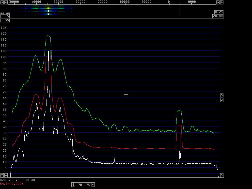 Fig. 5. Slow keying of the IC706-MKIIG at 14 MHz.
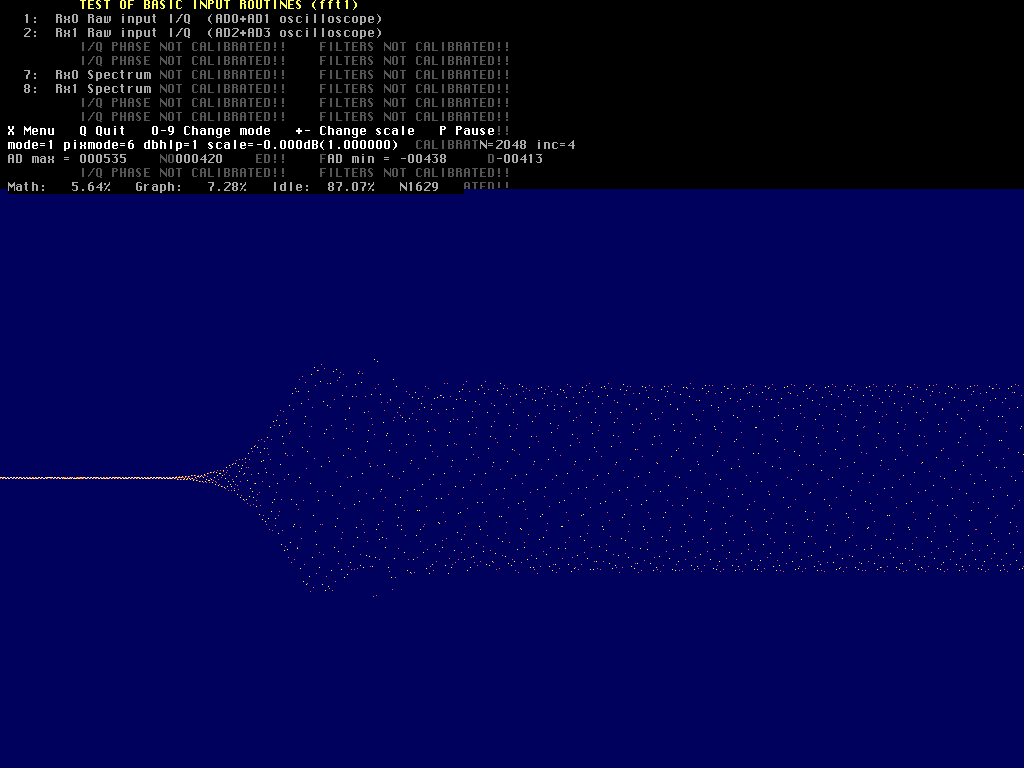 Fig. 6. Slow keying in the time domain.
It is pretty clear that the ALC has a fast attack, slow release level detector that modulates the signal with a very high bandwidth when the slow release time constant no longer keeps the gain reasonably near the correct level.
The idea to use ALC to regulate the gain in a transceiver is a bad one. The only decent way is to use the ALC as a protection circuit that never becomes active during normal operation. Whenever the ALC detects a signal above the proper level, the microprocessor or the operator should reduce the transmitter gain permanently. The level should be set/limited before the SSB filter after which the gain should be constant. Misuse of ALC seems to be very common, it causes a lot of splatter and other forms of interference. Using ALC for speech compression seems to be the most common origin of splatter on the amateur radio frequency bands.
For a discussion about the mis-use of ALC that is so common, look at The abominable ALC.
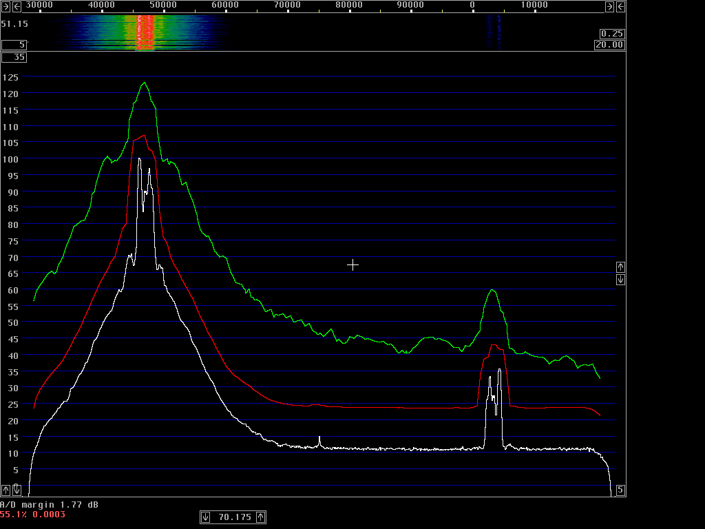 Fig. 7. SSB voice transmission of the IC706MKIIG at 14 MHz.
By saying aaaaaaaaaaa into the microphone and recording the spectrum it is possible to say that the problem is the ALC, not the linearity of the amplifiers. Figure 8 shows this. There is much less splatter even though the transmitter is operating with a very much compressed voice. Since the aaaaaaaaaa is at a constant high volume, the ALC voltage is more or less constant and does not introduce much wideband modulation.
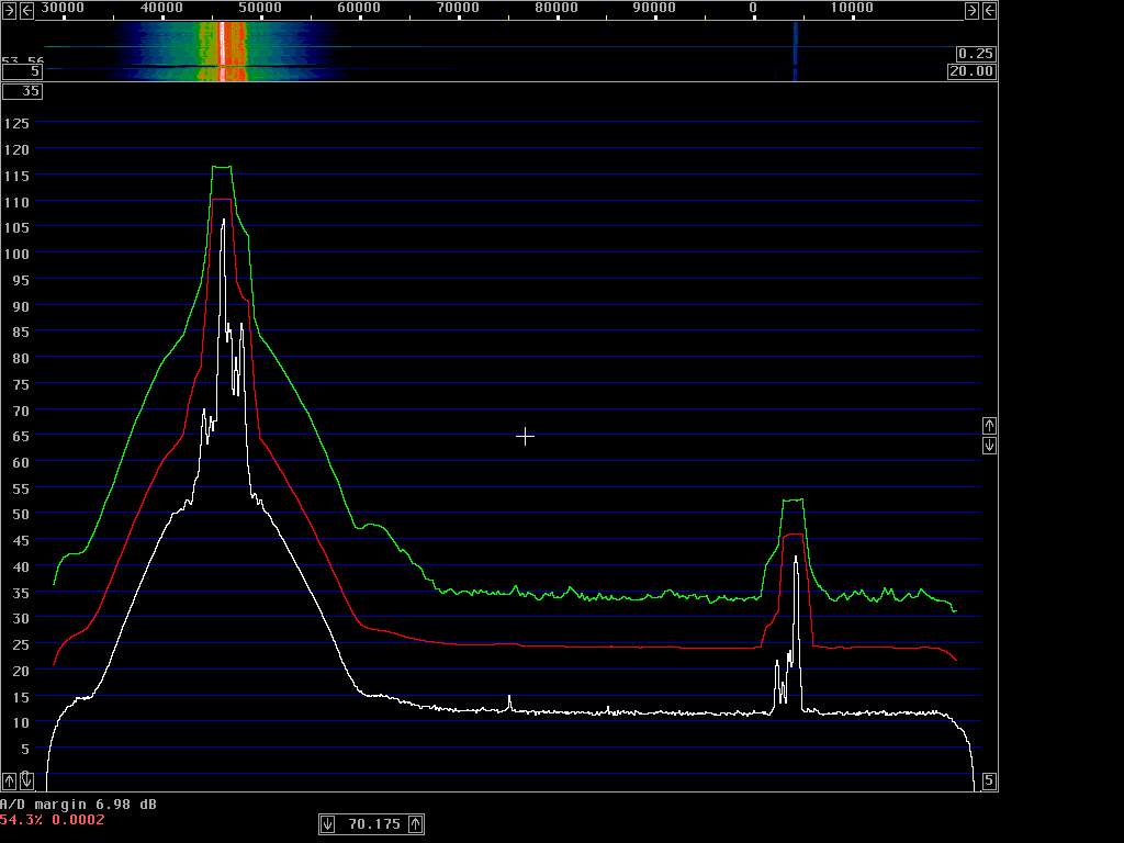 Fig. 8. Loud "aaaaaaaaaaa" in SSB mode keeps the
ALC voltage nearly constant with much less splatter as a result.
Fig. 8. Loud "aaaaaaaaaaa" in SSB mode keeps the
ALC voltage nearly constant with much less splatter as a result.Figure 9 shows the spectrum when the ptt button is pressed and released repeatedly. It seems to be a common problem that large wideband transients are transmitted when the ptt button is used. The transceiver designers do not make sure that the tx amplifier chain is running properly before the input signal is applied. When the ptt button is operated in CW mode with the key up, no interference at all is generated.
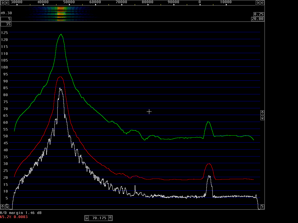 Fig. 9. The PTT button generates strong transients that
cause interference over 100kHz or more.
Fig. 9. The PTT button generates strong transients that
cause interference over 100kHz or more.The gain distribution is fine, figure 10 shows the noise floor emitted in ssb mode when the ptt button is kept pressed and there is no voice into the microphone. The noise floor is 101.7 below the peak power in 2.4 kHz bandwidth which corresponds to 135.7 dBc/Hz.
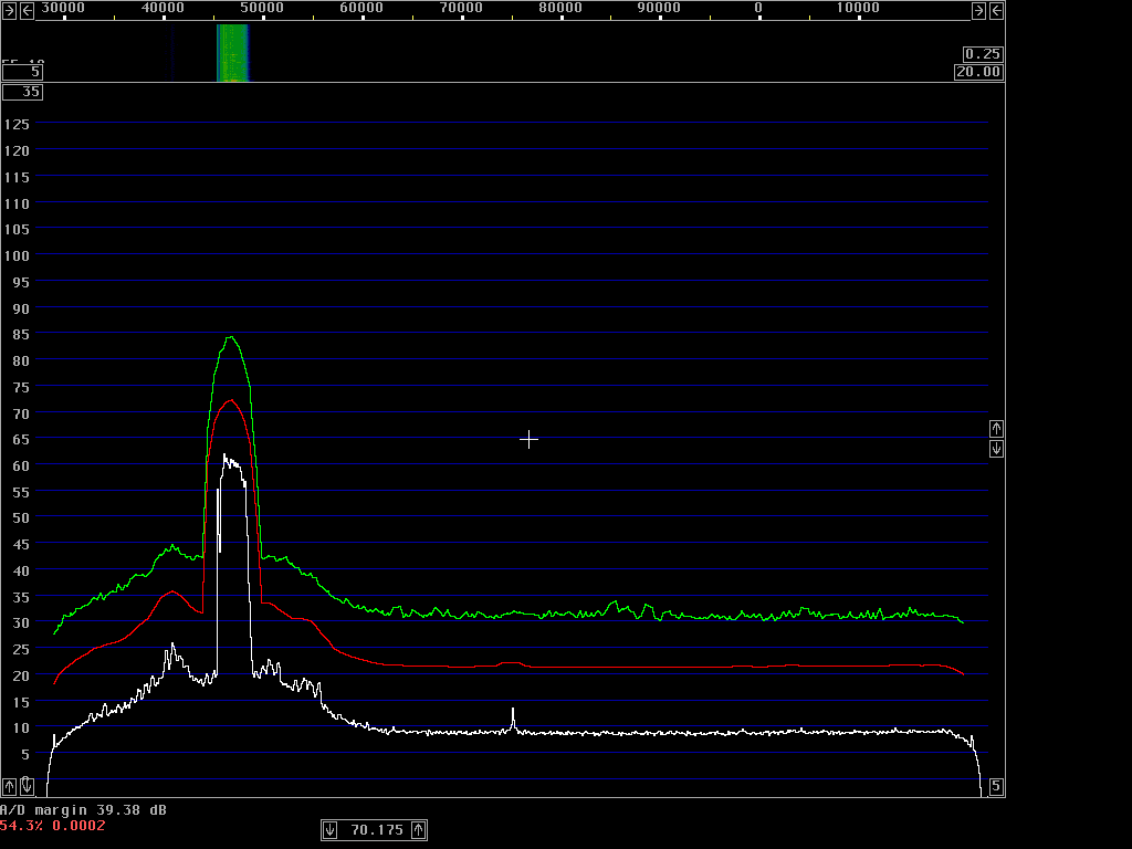 Fig. 10. SSB transmission with silence into the microphone.