Please read this page Using the HP8970A with circulators. before you read the text below.
General.
The computer can set the 8970A to performe the same measurements that were performed manually through commands and reads on the HPIB bus. For that purpose we have used Agilent VEE Pro.It is convenient to set the number of averages to 128 because that gives a new value every 5 seconds. There are two precision thermometers and the control program will update Tcold and Tloss before each measurement.
The computer makes averages of the measured data which is transferred with two decimals as Te. This way there is negligible contributions from rounding errors. The computer can average over long times and that gives very small statistical variations which makes all the systematic errors visible.
The idea is to use the setup to compare low noise amplifiers with high accuracy. For that a high degree of stability is required.
Temperature dependencies.
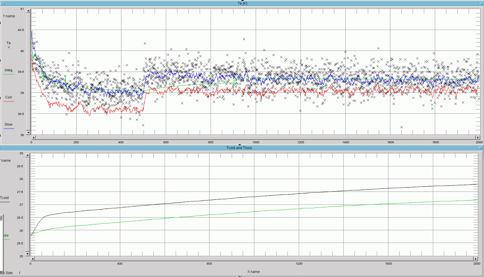
Heating the noise head or heating the 3 dB attenuator causes a lower indicated value for Te. See figures 1 and 2.
| |||||||||||||||||||||||||||||||||||||||||||||||||||||||||||||||||||||||||||||||||||||||||||||||||||||||||||||||||||||||||||
| Figure 1. Noise temperature vs time. Ignore the green line. It is the average over all points 0 to N which is not meaningful here. | |||||||||||||||||||||||||||||||||||||||||||||||||||||||||||||||||||||||||||||||||||||||||||||||||||||||||||||||||||||||||

| |||||||||||||||||||||||||||||||||||||||||||||||||||||||||||||||||||||||||||||||||||||||||||||||||||||||||||||||||||||
| Figure 3. Tcold and Tloss during the capture of figure 1. | |||||||||||||||||||||||||||||||||||||||||||||||||||||||||||||||||||||||||||||||||||||||||||||||||||||||||||||||||||
At about point 180 in figures 1 and 2 the temperature of the 3 dB attenuator was increased by about 14 degrees by use of an hot air gun. It is obvious that the termometer response is quite a bit faster than the internals of the attenuator. The change in Te is about 2.5 K but that is mostly because of the temperature differences between the thermometer probe and the attenuator internals. After the transcient in Te one can estimate that a 5 degree change in Tloss causes a 0.5 degree change in Te. This estimation is very uncertain however. At about point 1100 in figures 1 and 2 the temperature of the noise head was increased by about 30 degrees using the hot air gun. The associated improvement in the indicated Te value was about 7 degrees. At about point 1800 the LNA was heated. It is obviously sensitive. After it was heated it was placed a little differently. Obviously with a somewhat higher temperature as a result. The total time for figures 1 and 2 was about 9 hours. The LNA temperature.The temperature of the LNA affects its noise temperature. To eliminate that problem the LNA (L LNA by AD6IW) was put in a plastic bag and immersed in a mixture of ice and water. That made Te more stable and 3 K lower.Even temperatures.Even with the LNA in ice/water the Te variations with room temperature were irregular. This can be attributed to different temperatures on different parts.Directing the air stream from a fan on the noise head and circulator arrangement improves, but that is not enough. To reduce this problem the circulators and noise head arrangement was put inside a box made from 20 mm polystyrene foam sheets. The thermal isolation made things better, but not good. It turned out to be necessary to put a small fan inside the polystyrene box. With two polystyrene boxes, one for the noise head / circulators and another for ice/water one would expect no immediate effect from opening a window. That is not quite correct however. The losses in the cable between the boxes changes its temperature and that is immediately visible on Te. The original 3 mm semirigid cable was therefore replaced by a 6 mm cable to reduce this effect and the room temperature was kept constant while the effect of temperature changes inside the noise head / circulator box were studied. Te vs temperatures.One would expect that the indicated Te value would not change much when the temperatures of the noise head and the 3 dB attenuator are slowly changed inside the polystyrene box. That is not true at all however. See figure 4. | |||||||||||||||||||||||||||||||||||||||||||||||||||||||||||||||||||||||||||||||||||||||||||||||||||||||||||||||||

| |||||||||||||||||||||||||||||||||||||||||||||||||||||||||||||||||||||||||||||||||||||||||||||||||||||||||||||||
| Figure 4. Tcold, Tloss and Te. | |||||||||||||||||||||||||||||||||||||||||||||||||||||||||||||||||||||||||||||||||||||||||||||||||||||||||||||

| |||||||||||||||||||||||||||||||||||||||||||||||||||||||||||||||||||||||||||||||||||||||||||||||||||||||||
| Figure 5. Tcold, Tloss and Te. Continuation of figure 4. | |||||||||||||||||||||||||||||||||||||||||||||||||||||||||||||||||||||||||||||||||||||||||||||||||||||||
|
| |||||||||||||||||||||||||||||||||||||||||||||||||||||||||||||||||||||||||||||||||||||||||||||||||||
| Figure 6. Tcold, Tloss and Te. Continuation of figure 5. | |||||||||||||||||||||||||||||||||||||||||||||||||||||||||||||||||||||||||||||||||||||||||||||||||
Figures 4 to 6 were captured like this:
The number within brackets [ ] is the approximate X coordinate. Each point is about 5 seconds and the total time about 38 hours. Ice was filled in the ice/water container for the LNA about every 6 hours. While generating the images 4 to 6 the VEE program also wrote all the data to a file on the hard disk. Figure 7 shows all the 27419 data points and it is obvious from the figure that smoothing and reduction of the number of points will be appropriate. A reduction of the number of points by a factor of 32 gives the result displayed in figure 8. | |||||||||||||||||||||||||||||||||||||||||||||||||||||||||||||||||||||||||||||||||||||||||||||||

| |||||||||||||||||||||||||||||||||||||||||||||||||||||||||||||||||||||||||||||||||||||||||||||
| Figure 7. The 27419 data points in figures 4 to 6 displayed in a way that gives an idea about the statistics of the Te data. | |||||||||||||||||||||||||||||||||||||||||||||||||||||||||||||||||||||||||||||||||||||||||||

| |||||||||||||||||||||||||||||||||||||||||||||||||||||||||||||||||||||||||||||||||||||||
| Figure 8. The data of figure 7 contracted to 856 points. | |||||||||||||||||||||||||||||||||||||||||||||||||||||||||||||||||||||||||||||||||||||
Each division on the X-axis in figure 8 is 25 points which corresponds to 800 points in figures 4 to 6. Minimum Tcold at 10 happens one division before the maximum in indicated Te. That is a delay of about 1 hour. It is also clear that the errors are much larger at low temperatures than at high temperatures. The reason for the change in Te is most probably due to the PCB inside the noise head which is thermally isolated from the RF parts and the thermometer. It seems that the current through the noise diode gets lower as the temperature decreases and that this effect is delayed and strongly non-linear. | |||||||||||||||||||||||||||||||||||||||||||||||||||||||||||||||||||||||||||||||||||

| |||||||||||||||||||||||||||||||||||||||||||||||||||||||||||||||||||||||||||||||||
| Figure 9.The red points is a correction that is computed from from the temperatures. The curve is the data of figure 8 extended with the data from a restart of VEE. | |||||||||||||||||||||||||||||||||||||||||||||||||||||||||||||||||||||||||||||||
The first correction, the red curve in figure 9 is computed like this: Tcd[ i ]=0.99587 * Tcd[ i - 1 ] + 0.00413 * Tcold[ i ] Tcorr[ i ] = 39.04 + 30.92 * 0.93125Tcd[ i ] + 0.26 * Tcold[ i ] - 0.1268 * Tloss[ i ] There might be too many parameters and to many decimals, but this is a reasonable starting point. Figure 10 shows a recording with the correction implemented in VEE. | |||||||||||||||||||||||||||||||||||||||||||||||||||||||||||||||||||||||||||||

| |||||||||||||||||||||||||||||||||||||||||||||||||||||||||||||||||||||||||||
| Figure 10. Output from VEE May 12 to May 16. In the upper window the blue curve is the smoothed reading from the HP8970A (raw data is black.) The red curve is the reading obtained after applying the first correction. | |||||||||||||||||||||||||||||||||||||||||||||||||||||||||||||||||||||||||
The noise head and circulator arrangement was modified by the addition of several thick aluminium rods attached to the 20 mm base plate with the purpose of making the vertical thermal distribution better inside the foam polystyrene box. As a result the difference in the indicated temperatures for Tcold and Tloss shows a smaller variation as a response to temperature changes. Actually they are probably nearly equal and the difference is probably just a calibration error on the thermometers. Table 1 gives the sequence of events in the recording of figure 10: | |||||||||||||||||||||||||||||||||||||||||||||||||||||||||||||||||||||||
Day Time   Point  Ambient        Event
12  17.04      0     -     Start
12  18.00    530   24.7      -
12  20.37   2020   24.6    Base plate heated by 2W.
12  23.15   3520   24.3    Heating on base plate switched off
13  00.56   4480   24.2    Window opened.
13  01.56   5050   19.1      -
13  03.15   5830   18.1    Window closed
13  11.00  10200   24.7      -
13  12.50  11320   25.1      -
13  14.00  11910   25.5      -
13  16.00  13050   25.2      -
13  18.20  14600   24.8      -
13  19.40  15230   24.4      -
13  20.35  15550   24.7    CPU load 100% causes error on thermometer readings.
                           This was caused by VEE accidentally set to debug mode.
                           Only Tcold was affected.
13  20.40  15600   24.7    A 1.5 kW heating fan was switched on to increase the
                           ambient temperature. Doors closed.
13  23.15  17060   27.1       -
14  00.55  18010   27.6       -
14  04.15  20000   28.0    Heating fan switched off.
14  10.06  23290   26.0    Doors opened.
14  11.22  24000   25.2       -
14  12.45  24800   25.2       -
14  14.15  25690   25.7    Windows opened, doors closed.
14  14.55  26050   17.6       -
14  16.17  26840   15.9       -
14  17.30  27530   13.9    Windows closed.
14  17.40  27620   17.9       -
14  19.20  28580   20.1       -
14  20.45  29390   21.5       -
14  23.00  30670   22.3       -
15  00.15  31370   22.6       -
15  01.00  31800   22.1       -
15  03.50  33470   21.7       -
15  09.45  36860   24.0    Room warmed by sunshine.
15  11.10  37670   24.9    Doors opened.
15  13.15  38830   24.3       -
15  17.07  41060   24.8    Base plate heated with 75 W for about 2.5 minutes.
                           Power then adjusted for Tcold to stay
                           around 31.2 degrees.
15  17.20  41180   24.8    Power heating the base plate left at 1.15 W.
15  17.51  41480    -      Thermometer for Tloss failed due to
                           empty battery.
15  21.12  43380   24.1    Power off to base plate heating.
15  21.34  43590    -      Batteries in thermometers replaced.
16  08.50  50000    -      Automatic stop.
| |||||||||||||||||||||||||||||||||||||||||||||||||||||||||||||||||||||
Table 1. Details about the data shown in figure 10. | |||||||||||||||||||||||||||||||||||||||||||||||||||||||||||||||||||
Figure 11 shows the data of figures 9 and 10 with the first correction. It is obvious that the data of figure 10 is shifted by about 0.5 K while the variations with temperature are reasonably accurate. | |||||||||||||||||||||||||||||||||||||||||||||||||||||||||||||||||

| |||||||||||||||||||||||||||||||||||||||||||||||||||||||||||||||
| Figure 11. The first correction applied to the data of figures 9 and 10. | |||||||||||||||||||||||||||||||||||||||||||||||||||||||||||||
The correction curve in red is blue in certain ranges where the data is judged to be inaccurate for various reasons. It is for example obvious that the rapid reduction in observed Te at about 41060 is an artifact. The thermometer senses a rapidly rising temperature, but the internals of the noise head does not rise nearly as fast so the Te correction sent to the 8970A is incorrect. The model is not valid for very fast temperature changes. By use of least squares fitting to the red parts of the correction curve in figure 11, the following final corrections were obtained: Tcd[ i ]=0.9965 * Tcd[ i - 1 ] + 0.0035 * Tcold[ i ] Tcorr[ i ] = X + 42 * 0.88Tcd[ i ] X=45.95 for the figure 9 part and X=45.42 for the figure 10 part. The shift of 0.53 K may be due to a different temperature profile, but could also be due to some change that I have now forgotten. The much simpler final correction gives a good agreement with measured data as shown in figure 12. | |||||||||||||||||||||||||||||||||||||||||||||||||||||||||||

| |||||||||||||||||||||||||||||||||||||||||||||||||||||||||
| Figure 11. The final correction applied to the data of figures 9 and 10. | |||||||||||||||||||||||||||||||||||||||||||||||||||||||
For application in the VEE program X=-1. Tcorr[i] then becomes a correction to subtract from the Te values supplied by the 8970A. Settling time.When the HP8970A is started from cold and the fan in the noise head and circulator box has been switched off for a long time, it takes several hours for temperatures to become stable. The power dissipation of the noise head and the fan bring the temperature inside the box about 3 degrees above ambient. Due to the temperature compensation it is not necessary to wait for a stable temperature.Figure 12 shows a cold start. Note that Tcold and Tloss are nearly equal when the measurements starts. It takes about 10 minutes until the difference between Tcold and Tloss reaches its normal value 0.6 degrees. | |||||||||||||||||||||||||||||||||||||||||||||||||||||
| |||||||||||||||||||||||||||||||||||||||||||||||||||
| Figure 12. The 8970A as well as the fan in the noise head box have been switched off for 6 hours before this measurement was made. | |||||||||||||||||||||||||||||||||||||||||||||||||
It takes about 30 minutes for the exponential fall-off from the initial 39.6 K to the stable value 38.6 K. That is from the red curve, the corrected Te in figure 12. There is however another problem. This is clearly visible in figure 12 at about point 510. That is 54 minutes after start and here the measured value of Te makes a jump of 0.5 K. This is a real effect, figure �13 shows another cold start. | |||||||||||||||||||||||||||||||||||||||||||||||

| |||||||||||||||||||||||||||||||||||||||||||||
| Figure 13. Another cold start. Here the fan has been running all the time but the 8970A was switched off for a couple of hours. | |||||||||||||||||||||||||||||||||||||||||||
The HP8970A NF meter is not designed to be used for very high precision measurements. The unit has an analog power detector which is good, but far from ideal. There are amplifiers and attenuators that make sure that the power detector operated in a region where its linearity is good, but when the gain changes to cause the detector to operate at the other end of its linear region, the computed power ratio becomes different. That is the reason for the step in Te after cold start. Amplitude dependency of measured noise temperatuer.Table 2 shows the measured Te in a setup where the signal level can be stepped in 1 dB steps. The DUT is followed by a G4DDK amplifier through a 1 dB loss cable for a second stage NF in the order of 1.2 dB. A stepped attenuator is inserted between the G4DDK amplifier and the 8970A. The DUT is a L LNA from AD6IW. The gain is about 23 dB. The DUT is kept at zero degrees Centigrade in ice/water. Te is also measured at the input of the G4DDK amplifier and the contribution from the second stage 21.5 dB (141 times lower) is also shown in the table. Since the zero point of the Te scale is unknown, it is reasonable to replace the measured value for the G4DDK amplifier without attenuator (39.44 dB) by the cable loss (1.04 dB) plus a guessed NF for the amplifier, 0.2 dB. In total 1.24 dB. The corresponding Te is 96 K. The contribution at the DUT input with 21.5 dB gain is then 0.68 K. | |||||||||||||||||||||||||||||||||||||||||
Nominal       System Te    Te 2nd stage   Te 2nd stage      Corrected
attenuation   Measured      Measured        Guessed         System Te
  (dB)           (K)          (K)             (K)           (K)
    0           39.44       75.16           96.0           38.96
    1           39.47       75.09           96.0           38.99
    2           39.25       75.03           96.0           38.77
    3           39.18       74.83           96.0           38.70
    4           39.35       75.00           96.0           38.87
    5           38.85       75.19           96.0           38.37
    6           38.81       75.55           96.3           38.33
    7           38.94       75.96           96.7           38.46
    8           39.05       76.60           97.2           38.56
    9           39.30       76.78           97.7           38.81
   10           39.51       77.25           98.2           39.02
   11           39.64       78.28           99.3           39.14
   12           39.35       79.48          100.5           38.85
   13           39.20       80.31          101.3           38.69
   14           39.18       82.16          103.2           38.66
   15           38.83       84.34          105.3           38.30
   16           38.80       87.17          108.2           38.26
   17           38.91       90.65          111.7           38.35
   18           38.94       95.34          116.3           38.36
   19           39.73       99.91          120.9           39.13
   20           39.62      105.5           126.5           38.99
   21           39.53      116.5           137.5           38.84
   22           39.76      128.1           149.1           39.01
   23           39.33      141.5           162.5           38.52
   24           39.37      160.1           181.1           38.46
   25           39.51      162.9           195.0           38.54
   26           39.23      211.6           232.6           38.07
   27           39.47      245.6           266.6           38.14
   28           39.75      291.6           312.6           38.19
   29           40.11      342.6           363.6           38.29
   30           40.53      402.0           423.0           38.42
   31           40.67      443.0           464.0           38.35
   32           41.10      541.1           562.1           38.29
   33           41.67      658.6           679.0           38.28
   34           42.58      819.2           840.2           38.38
   35           43.65     1012.2          1033.2           38.48
| |||||||||||||||||||||||||||||||||||||||
Table 2. The system noise temperature reported by the 8970A at different signal levels. The last column has a compensation for the effect of the second stage noise contribution. | |||||||||||||||||||||||||||||||||||||
Figure 14 shows the last column of table 2. It is obvious that there is an error with a periodicity of 5 dB in the signal level and a peak amplitude of about 0.8 K. There is a BNC connector at the rear panel of the 8970A labelled DET. The detector output has the same periodicity of 5 dB on input signal level. That is the step size of the AGC that uses switched attenuators. | |||||||||||||||||||||||||||||||||||

| |||||||||||||||||||||||||||||||||
| Figure 13. The Te value obtained from the 8970A as a function of the signal level. | |||||||||||||||||||||||||||||||
To investigate the non-linearity of the power detector the signal level was adjusted in 0.5 dB steps. There was sufficient gain to ensure that the system noise figure was unaffected. The result is shown in figure 14 and table 3. | |||||||||||||||||||||||||||||
Nominal UDET System Te attenuation Measured (dB) (V) (K) 0 0.803 47.59 0.5 0.757 47.22 1.0 0.723 47.12 1.5 0.677 46.75 2.0 0.637 46.66 2.5 0.594 46.59 3.0 0.571 46.46 3.5 0.534 46.28 4.0 0.498 46.33 4.5 0.474 46.30 5.0 0.454 46.26 5.5 0.423 46.41 | |||||||||||||||||||||||||||
Table 3. The non-linearity of the power detector. Te should not be affected by the signal level. | |||||||||||||||||||||||||

| |||||||||||||||||||||
| Figure 14. The indicated system noise temperature of the 8970A depends on analog power detector. This is the data of table 3. | |||||||||||||||||||
Table 3 and figure 4 suggest that the 8970A should be operated with a DC level of 0.500 V on the detector output. There are however many gain settings that satisfy this requirement. There could be non-linearity problems in IF amplifiers and elsewhere which motivate a study of the indicated Te at the different levels that produce 0.5 V on the detector output. Three series of measurements are listed in table 4. DUT, Dut+filter and system without the DUT. The filter has a bandwidth of 30 MHz and is flat over 10 MHz around 1296 MHz. The DUT is a G4DDK amplifier with a L/S amp by AD6IW as the second stage followed by a PSA4-5043 as the third stage. Then there is a stepped attenuator followed by a circulator and a AD6IW amplifier that sends the signal to the 8970A and a spectrum analyzer through a 3 dB coupler. The readings on the spectrum analyzer gives the nominal attenuation values and the gain as 39.0 dB. | |||||||||||||||||
Nominal       Te without    Te with   Te 2nd stage   Corrected Te
attenuation     filter      filter     with filter   with filter
  (dB)           (K)          (K)         (K)           (K)
    0           33.98       32.04        41.96          32.05
   5.1          33.08       32.29        43.68          32.30
  10.5          33.10       31.99        54.25          32.00
  14.7          33.19       32.34        67.38          32.35
  19.9          33.46       32.07        127.9          32.09
  25.0          33.30       32.30        347.2          32.26
  30.3          33.51       32.10        1030           31.97
  35.1          33.53       32.73        3367           32.30
  40.2          34.29       33.15
  45.0          36.63       35.67
| |||||||||||||||
Table 4. Measurements with UDET = 0.500 V. | |||||||||||||
The system has maximum gain at about 1150 MHz without the filter. The filter reduces the bandwidth by about a factor of 10 from 300 MHz to 30 MHz and it also avoids the about 5 dB higher level around 1150 MHz. White noise has a high crest factor, it is clear from table 4 that some amplitude limiting happens at maximum gain without the filter at 0 dB attenuation. The corrected system Te with the filter alternates between two values, 32.05 and 32.3. That is presumably due to a saturation problem in the IF section which is responsible for the 5 dB stepping. Figure 15 shows Te and UDET when the level is stepped over a 11.5 dB range. It is quite obvious that certain ranges of signal levels should be avoided when high precision is desired. br> | |||||||||||

| |||||||||
| Figure 15. Stepping over a 11.5 dB range shows that certain input levels should be avoided. In some cases the error is large when UDET is large. | |||||||
Table 5 shows signal levels and the automatic RF and IF gain/attenuator settings as well as indicated Te with a high level, 0.85 V on the power detector. | |||||
Level in RF IF 1 MHz Te setting attenuation (dBm) (K) (dB) (dB) -24.0 - -20 30 -28.5 32.78 -10 35 -33.6 31.89 -10 30 -37.8 32.96 0 35 -42.8 32.12 0 30 -48.4 32.97 +10 35 -53.5 32.12 +10 30 | |||
Table 4. Measurements with UDET = 0.85 V. Input levels that use 35 dB IF attenuation ( code = 111) should be avoided for precision measurements. | |
Discussion.The HP / Agilent 8970A noise figure meter is designed to provide fast and convenient measurements with limited accuracy for industrial purposes. The investigations above show that the instrument can be used for highly accurate measurements of relative noise temperatures.The instrument measures power ratios. By avoiding 35 dB IF attenuation and selecting a signal level that produces 0.50 V DC on the detector output one operates the detector in its most linear region. Then small errors in the level will not affect the result. The purpose is to compare amplifiers with very low noise figures so the Y-factors are very similar for all test objects. Whether the Y-factor is 10.68 dB or 10.54 dB is what we want to measure with high accuracy. Such a difference corresponds to 10 K. Linearity errors will have an extremely small effect on the differences between similar Y-factors. The 8970A is run uncalibrated. That means that it measures system NF. The procedure to use is to first insert the DUT, then set the manual attenuators for a detector level of 0.5 V, making sure that the IF attenuator is in the 30 dB position. Then press reset in the VEE program and wait for about 2 minutes while 20 readings from the 8970A are averaged. That gives an accuracy of about 0.1 K. Finally, remove the DUT and measure the signal level to get the gain of the DUT and also the system noise temperature that was present on the output side of the DUT. This noise temperature does not have to be very accurate because its contribution will be divided by the DUT gain. |