Grounded cathode amplifiers
A vacuum tube does not need any power (nearly) to swing the voltage of the control grid in a grounded cathode circuit, but as soon as the grid becomes positive with respect to the cathode, grid current starts to flow, and drive power is consumed.In a high power amplifier, the grid is normally operated positive with respect to the cathode during a small part of the cycle at full power. Real power is then consumed by the grid circuit, and it is used to heat the control grid and the grid resistor (or grid supply).
When the drive level is reduced, the grid current gradually disappears and then the grid circuit is no longer loaded by the tube. The variable load from the grid may cause the output power to vary with the input power in a very non-linear way, something like this:
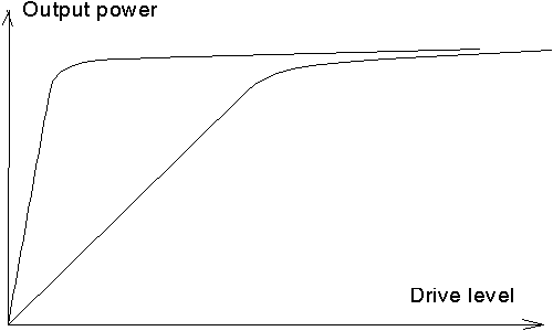
The two curves correspond to grid circuits having different
sensitivity to loading.
At low frequencies there are many ways to produce a low
impedance source to drive the grid, but particularly at higher frequencies
the easiest way is to load the grid circuit by a resistor to prevent
the gain from rising when the drive level is reduced.
Omitting this resistor may cause a very high SWR at low drive
levels, with unpredictable behaviour of the driver stage as a result.
Grid circuit efficiency
Since the grid circuit should be loaded by a resistor for linearity reasons, there is no reason to look for efficiency on the grid circuit. Still it is a good idea to design the LC circuit on the grid side as if efficiency was important, but the reason is only thermal stability. Thick wire (sheet metal) with good thermal conductivity keeps temperature low and even. Largest possible inductance and a small tuning capacitor increases the bandwidth and makes the tuning less critical. Some resistors between grid and cathode from a RF point of view should be inserted to make the Q of the grid circuit stay at reasonably low values even when no grid current flows. These resistors may be selected to consume 2 to 5 times less power than actually used to generate the grid current in the tube. If you are going to design your own amplifier, look at this example. A grid circuit for QBL5/3500Setup for practical adjustment of the grid circuit
First decide how you like to drive the tube at maximum output. As an example, a single 4CX250B may be operated with 25 milliamperes at -90 volts in class C to produce 390W output at 500W input with a plate voltage of 2000 volts. (Do never design an amplifier for pure class C - design it for variable class to avoid keying clicks)To produce 90 volts with 25 milliamperes, you need a resistor of 3.6 kilo ohms. The resistor needs to dissipate 2.25W. Connect the heater voltage to the tube BUT DO NOT CONNECT ANY OTHER VOLTAGE. Connect the 3.6 k resistor instead of the control grid supply, and leave the wires for the plate and the screen grid hanging unconnected as in the figure below.
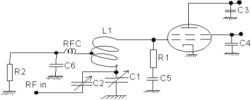
At VHF, a grounded cathode amplifier is usually a tetrode, but if you are an extremist building neutralised grounded cathode amplifiers with triodes - just disregard everything about the screen grid.
After having connected as indicated by the figure, and with the heater voltage on, switch on some drive power. Measure the voltage across R2 (3.6 kilo ohms with the example above). Any RF voltage between grid and cathode will be rectified and can be monitored as a DC voltage across this resistor. The task is now to play around with the components for this voltage to reach the desired value, which also means that the current has reached the desired value.
The figure does not give any details on anode and screen grid circuitry. They are treated elsewhere: Building High Power Amplifiers, The Tank Circuit The only aspect of importance here is the decoupling capacitors, and that anode and screen are left open from a DC point of view. BE CAREFUL NOT TO TOUCH C3 or C4. They become charged when you feed RF onto the control grid, and if you touch them, the electric shock may cause you to destroy valuable things, including yourself, particularly if the tube is a big one like QBL5/3500 aiming at class C.
Simpleminded theory on the grid circuit
The resonance of the grid circuit is uses L1 as the inductor, and the cathode to grid capacitance of the tube in series with C1+C2 as the capacitor. Make C1 2 to 5 times larger than the tube capacitance, a too small value gives rise to high voltages and may cause arcing.In the example, 90 volts, 25 milliamperes, the RF voltage between the control grid and the cathode is about 80 volts RMS. The current flows at the voltage peaks so the power taken from the RF signal is 1.414 * 80volts * 0.025 amperes = 2.8 W. 2.25W is used to heat R2 and the rest, 0.55 W is used to heat the grid.
The G1 current flows in short pulses. The loading they make to the G1 voltage corresponds to 2.3 kilo ohms. If R1 was made 2.3 kilo ohms, R1 would also consume 2.8 W of RF power from the grid circuit. In this example, 4.7 k ohms (1.5W) would be a reasonable value for R1.
If C1+C2 is 3 times bigger than the cathode to grid capacitor, the RF voltage across C1 is about 27 volts and the impedance level about 175 ohms (impedance goes as voltage squared)
Assuming we need 5 W to drive the amplifier (2.8 for the grid, 1.4 for R1 and 0.8 for losses) the current through C2 should be 0.31A because that is the current we get when taking 5 W from a 50 ohm source. The voltage at RF in is 15.8 volts, and it is in phase with the current through C2. The voltage across C2 has to be 90 degrees out of phase with the current as always for capacitors, so the 27 volts across C1 has to be 90 degrees phase shifted with respect to the 15.8 volts at the input. The voltage across C2 then becomes 31 volts using Pythagoras. For C2 we have 31 volts at 0.31 amperes, or 100 ohms, so at 144MHz a reasonable start value for C2 is 15pF.
Practical adjustment of the grid circuit
First match your driver stage to a 50 ohm load at the power level you think will be appropriate to drive the power amplifier. What you want is to have the driver adjusted to give maximum power when it is loaded by a 50 ohm load. If you have drive power enough, a 3dB or a 6dB attenuator can be inserted ( use some RG58 - it will attenuate reasonably high power levels without any problem)The grid circuit should have two controls, one for loading, and one for tuning. It may be an arrangement with C1 and C2 as in the figure above, or with a tuning capacitor and a variable inductive coupling with a moveable link, or in many other ways.
Just vary tune and load for maximum voltage across R2. Adjust the drive power if necessary, if the maximum you can reach by varying tune and load is to big or to small. But make sure the driver is still optimised for 50 ohms.
When this is done, you can insert a SWR meter between the driver and the power amplifier. The instrument will show that SWR is close to 1.0 and this is because you adjusted the driver to produce maximum power at the correct impedance. You may finally adjust tune and load on the grid of the power amplifier, while adjusting the drive power for the desired grid voltage and current.
If you start the procedure just by looking at the SWR meter, you may run into a difficult situation with infinite SWR, adjustments may affect both forward and reflected power very similarly.
The procedure described here is very safe. Even if the grid circuitry is completely wrong in a new amplifier design, with both tuning and loading very far from reasonable values, you will easily see in which direction to go in number of turns, moving links, changing capacitor values or any other modification needed to make the grid circuit operate as intended.
Neutralisation
Sometimes there is coupling between the grid circuit and the plate circuit. This coupling may be due to the capacitance between g1 and the anode, but it may also be because of poor g2 decoupling or some common current path for the input and output circuits. If this coupling is strong enough, and has the right phase, the amplifier will become an oscillator.The example above, with 4CX250B has a gain of about 20dB at full output. Full output is in a saturated condition (class C), and the gain is a good deal greater at lower drive levels. With about 35 volt RMS on the control grid the output power is about 300W. The input impedance would no longer be 50 ohms since the grid circuit is no longer loaded by any grid current (class AB, with - 55 volts on the grid). The input power would be the 0.6W needed to produce 55 volts across R1 (or slightly more), so the gain is nearly 30dB. If R1 is omitted, the gain can easily become 45dB in a class AB amplifier - remember, the purpose of R1 is to keep the gain down at low power levels to avoid keying clicks when running CW.
With a maximum gain of 30 dB in the amplifier, the coupling between the input and output should be weak enough to cause an attenuation of at least 40 dB when a small signal is transmitted through the amplifier without any voltages on.
When checking the attenuation through the amplifier, first make sure that it is properly tuned on both the grid and the plate side. Tune the plate side without high voltages as described as described here Cold adjustment of tuning and loading of the tank circuit
Measure the attenuation through the amplifier with a 50 ohm source and load. It does not matter in which direction you send the signal. With no voltages applied, the power amplifier is just a bunch of passive components, R,L and C and the attenuation is independent of the signal direction.
If you do not have access to instruments, just connect the power amplifier between your antenna and receiver, and ask some local amateur to send a signal in your direction. Then find some way to find out by how much the received signal is attenuated by the power amplifier. (Use attenuators, or calibrate the S-meter)
If the attenuation is not high enough, something has to be done.
You may lower the gain by reducing R1, this will give a marginal improvement, but if you have the drive power needed, why not?
Maybe changes in the screen grid decoupling will improve - it is easy to find out. Remember, there are no voltages present. You may short the screen grid to ground to see if a lower impedance would help.
If nothing else helps, (or if you are using a triode) the amplifier has to be neutralised. With the circuit diagram above, it can be done by adding a very small capacitance from the C1 end of L1 to the plate. This capacitance would be a small piece of wire that sticks into the anode compartment. Just play around with this small wire until you find a deep minimum in the weak signal transmitted through the amplifier. Remember that this capacitor is also parallel to C1, which may have to be retuned.
It is always possible to get a very high attenuation through an amplifier without voltages. If there is not a deep null at some well defined value on the neutralisation capacitor, the phase of the signal that is being coupled through the neutralisation capacitor is incorrect. Then the phase of this signal may be shifted by a LC link. What you want is simply to feed the same amount of power as the undesired coupling, but in the opposite phase and by use of reactive components. Just make sure that the phase shifter is broadbanded - so it does not create feedback in the wrong phase at some nearby frequency.