Homebrew Software to Control Multiple HPSDR Radios either Locally or from a Remote Location
by W3SZ 2/27/2015
C# application running under Windows 8.1. It will control up to 8 HPSDR radios are simultaneously . It is interfaced with N1MM Logger Plus
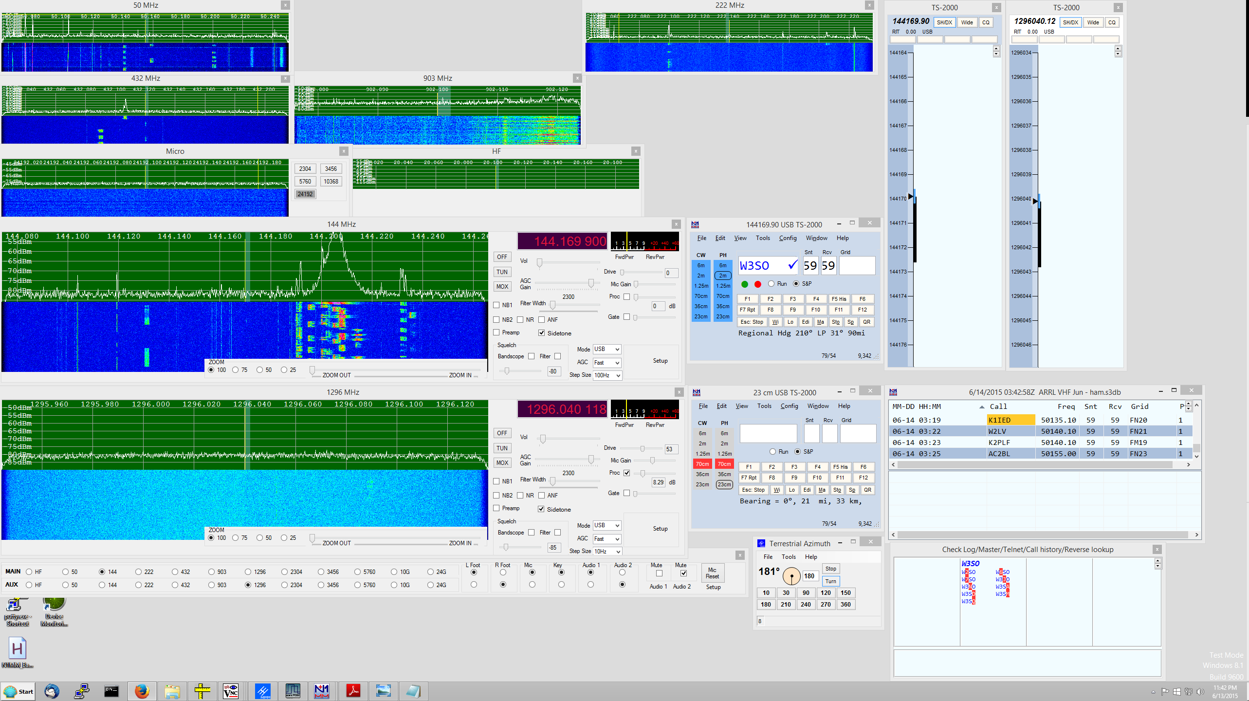
One of my interests in Amateur Radio is designing and implementing single-user multiband contest station setups. My specific area of interest is in systems for use during the VHF/UHF/microwave contests, covering the Amateur bands from 50 MHz through 24 GHz inclusive. I want to be able to run multiple software defined radios [SDRs] from a single computer, using the same screen/keyboard/mouse and also the same microphone/footswitch/speaker for all of them. The goal is to have individual, always-on bandscopes that simultaneously view the 50, 144, 222, 432, 903, and 1296 MHz bands, as well as a selected microwave band on a seventh SDR that covers each of the bands 2.3 through 24 GHz inclusive, to have another bandscope/controller for the HF bands, and to have the "radio be the bandscope". This minimizes the operational complexity of the system, by allowing the operator to instantly switch the "active radio" frequency to be that frequency on which an interesting signal has been spotted, on any one of the eight "bands", by clicking on the appropriate radio/bandscope. Also, I want all eight SDRs to appear as a single radio to the N1MM+ logging program, and for N1MM+ to automatically select the correct SDR when the operator switches bands within the N1MM+ program.
The paradigm is to have 8 radio GUI-bandscopes, one for each "band" as defined above. When not selected by the operator, the individual bandscopes appear as smaller windows, as you can see in the image above. When selected as either [1] the main radio or [2] the aux (liaison) radio, the selected bandscope will enlarge and move to the preselected screen position for the main or aux radio, depending upon which spot was selected for that band.
The software can either be used with the operator at the location of the radios, or with the operator at a remote location connected to the radio site by an ethernet link, either wired or wireless.
The software I've put together to accomplish this is based on the fantastic KISS Konsole software by Phil Harman, VK6PH, which works with the excellent HPSDR hardware. I wrote/modified/compiled the software using Visual Studio 2013, which is now a free product. The software was targeted at .NET Framework 4.
With the client software I wrote, there are 3 ways for the operator to select which band (radio) is active as either the main or the aux radio. The first way of selecting a band for operation is by mouse-clicking on the spectrum/waterfall of the small bandscope for a given band. Left-clicking will move the radio to the main radio position. Right-clicking will move the radio to the aux radio position.
The bands to be selected as main and aux radios
can also be selected from the Main Controller Bar, which as you can see in the
image above, is placed at the bottom of the screen. It is shown in more
detail below.

Clicking a "Radiobutton" for a band on the row of the bar labeled "Main" will bring that radio to the Main Radio position on the screen, and the expanded radio window thus exposed gives access to all of the main radio controls. This action will also make this band the main radio in N1MM+. Similarly, clicking a "Radiobutton" for a band on the "Aux" row of the bar will bring that radio to the Aux Radio position on the screen, and the expanded radio window thus exposed gives access to all of the aux radio controls. This action will also make this band the aux radio in N1MM+.
The third way of moving a radio to the main or auxiliary radio position is through N1MM+. Typing a frequency into the main radio entry window of N1MM+ will select the appropriate radio and place it in the main radio position on the screen and put it on that frequency. Similarly, typing a frequency into the aux radio entry window of N1MM+ will select the appropriate radio and place it in the aux radio position on the screen and put it on that frequency.
As you can see above, on the right side of the Main Controller Bar are Radiobuttons on both the Main Radio and the Aux Radio rows for "L Foot" (the left footswitch), "R Foot" (the right footswitch), the Microphone, the (CW) Key, and two audio channels ("Audio 1" and "Audio 2"). If the "L Foot" button on the Main Radio row is selected, then the left footswitch will be assigned to whichever radio is assigned as the main radio. Similarly for the "R Foot", "Mic", "Key", and the two audio channels. Of course, if the "L Foot" Radiobutton on the Aux Radio row is selected, then the left footswitch will be assigned to whichever radio is assigned as Aux Radio. For the operator using N1MM+, the experience is that of having a single radio with always-on bandscopes for all of the bands described above that covers every band from 50 MHz through 24 GHz, inclusive, with automatic bandswitching not only of antennas, but also of footswitches, microphone, key, and receive audio. The Main Controller Bar also allows the operator to mute either audio channel, or both [or none]. There are slight variations in the Main Controller Bar when the station is operated remotely. Only one footswitch is then used, and the audio channels are automatically assigned, so the right footswitch and the audio select radiobuttons do not appear on the Main Controller Bar when remote operation is selected.
I placed a video on YouTube that shows me running the client software through its paces.
The video is here. It is silent.
Basically, the design of the software does the following:
1. Splits
KISS Konsole (written by Phil Harman VK6PH with important contributions by
others) into a server and a client, designed for VHF and microwave use.
2.
The client controls multiple [up to 8 as configured] HPSDR Radios/servers:
50 MHz
144 MHz
222 MHz
432 MHz
903 MHz
1296 MHz
2-3-5-10-24
GHz
HF
3. The server sends Spectrum/Waterfall data to client
4. The
server sends CW sidetone data to client
5. The client controls the server, to
provide remote control [via ethernet] of all important radio functions
6. The
client interfaces with N1MM+, appearing to N1MM+ as one multiband radio covering
HF through 24 GHz
7. The client switches CW key/mic/2 footswitches/2 receive
audio channels between radios, either by using a separate USB hardware device or
more recently, with the remote capability added, via the ethernet with no need
for the separate USB hardware device
8. N1MM+
switches antennas among radios based on band data sent to N1MM+ from client
9. Added Adjustable FFT size 4096 to 524288 added to server
10.
Added "Wisdom" optimization of FFT calculations, performed first time program is
run
11. Added multiple waterfall palettes to client
12. Added computer
receive audio to server so that audio can be obtained without connection to
radio headphone jack, via Windows sound
13. Added zoom of spectrum/waterfall
to both server and client
14. Added CW sidetone to to both client and server.
CW works with hand key or WinKeyer output, or with typed CW from N1MM+ via WinKeyer.
15. Up/Down arrows in client will move frequency up/down by "Step Size".
This also allows the
ShuttlePRO v2 to act as a "knob" for frequency control.
16. Step Size can also be
set from the ShuttlePRO. The software is set up with the following key
assignments: a=1 Hz; b=10 Hz; c=100 Hz; d=1 kHz.
17. Mode can be set from
the ShuttlePRO. The software is set up with the following key assignments:
e=FM; f=USB; g=LSB; h=CWU; i=CWL.
18. Full remote operation using wired or wireless ethernet connection. Connections for CW, microphone audio, receive audio, footswitches are all made to the computer at the operator's location and these are "connected" via the ethernet to the ethernet ports of the individual radios. No physical connections to the microphone, CW key, or receive audio ports of the radios are needed. This remote capability makes unnecessary the OSX system that I had previously designed, and which I have used for hardware control for a number of years with earier versions of this software. That system is described here
The radio hardware used with the current system
is very similar to that used with the older system:
50 MHz SDR: HPSDR Hermes with the server
running on a 3.2 GHz Pentium 4
144 MHz SDR: Elecraft K3 with an HPSDR
bandscope running on a 3.1 GHz Core 2 Duo
222 MHz SDR: HPSDR Atlas/Ozy/Penelope/Mercury
stack running on a 3.1 GHz Core 2 Duo
432 MHz SDR: HPSDR Atlas/Ozy/Penelope/Mercury stack running on a 3.1 GHz Core 2 Duo
903 MHz SDR: HPSDR Atlas/Ozy/Penelope/Mercury stack running on a 3.1 GHz Core 2 Duo
1296 MHz SDR: HPSDR Atlas/Ozy/Penelope/Mercury
stack running on a 3.1 GHz Core 2 Duo
2.3-24 GHz SDR: HPSDR Atlas/Ozy/Penelope/Mercury
stack running on a 3.1 GHz Core 2 Duo
For switching of ancillary
hardware, this system originally used the same
Parallax Propeller USB Proto Boards that I used for the original OSX-based
control system. This system can still be used for local operation, but it
is not necessary as all of the switching and signal control is now done by
software and ethernet communication. This USB control system runs custom Spin applications
on the Propellers to set the assignments of the footswitch, microphone, CW keys
and receive audio channels to the main and aux HPSDR radios. This
hardwired system uses a USB
connection between the client computer and the Parallax Propellers, and thus is
applicable only to local operation. One Propeller
(lets call it the RadioManager) is used to control the footswitches, mic, and
key, and a second Propeller (lets call it the AudioManager) controls the receive
audio channels.
Each of the RadioManager Propeller's 28
outputs drives, through a 22K resistor, a 2N2222a which controls a
G6L-1P-DC12 relay
that provides the necessary switching between the radios of the left and right footswitches, microphone, and CW key [4 banks of 7 outputs each, to connect Left
Footswitch, Right Footswitch, Microphone, and CW Key each to one of the 7
radios (the HF radio is not controlled by this device)]. A single small printed circuit board from
Express PCB is used for each bank
of 7 outputs. The ExpressPCB PCB file for
the RadioManager boards is here.
The ExpressPCB schematic file for the RadioManager boards is
here.
I made the audio control interface a separate hardware
controller because a single Propeller did not have enough outputs to handle of
the the control channels. The
"custom Spin application on the AudioManager Propeller drives, through 22K resistors,
2N2222a transistors that control 3 banks of 7
G5V-2-H1-DC12 DPDT 12VDC relays each, so that I can switch
each of the 7 radios to any one of 3 audio output ports. There is one
"extra" relay bank available for expansion to 7 radios. The Express PCB
boards used for this task are similar to, but not identical to, those used for
the input device switching described above. Each of the two audio channels can be independently muted, as well.
The ExpressPCB PCB file for the Audio Controller boards is
here. The ExpressPCB schematic
file for the Audio Controller boards is
here.
Again, note that this hardware has been made redundant by the addition of remote
capability to this software. To initiate a session, each HPSDR radio and its associated
computer is powered up and a KISS Konsole server is started on the computer associated with
each HPSDR radio. These computers are "headless" and have no monitor,
keyboard, or mouse. If necessary, they can each be accessed via VNC, but
there is no VNC used during system operation, greatly reducing the required
network bandwidth. The client software and
N1MM+ are started on the control computer. One can then begin running the
bands.
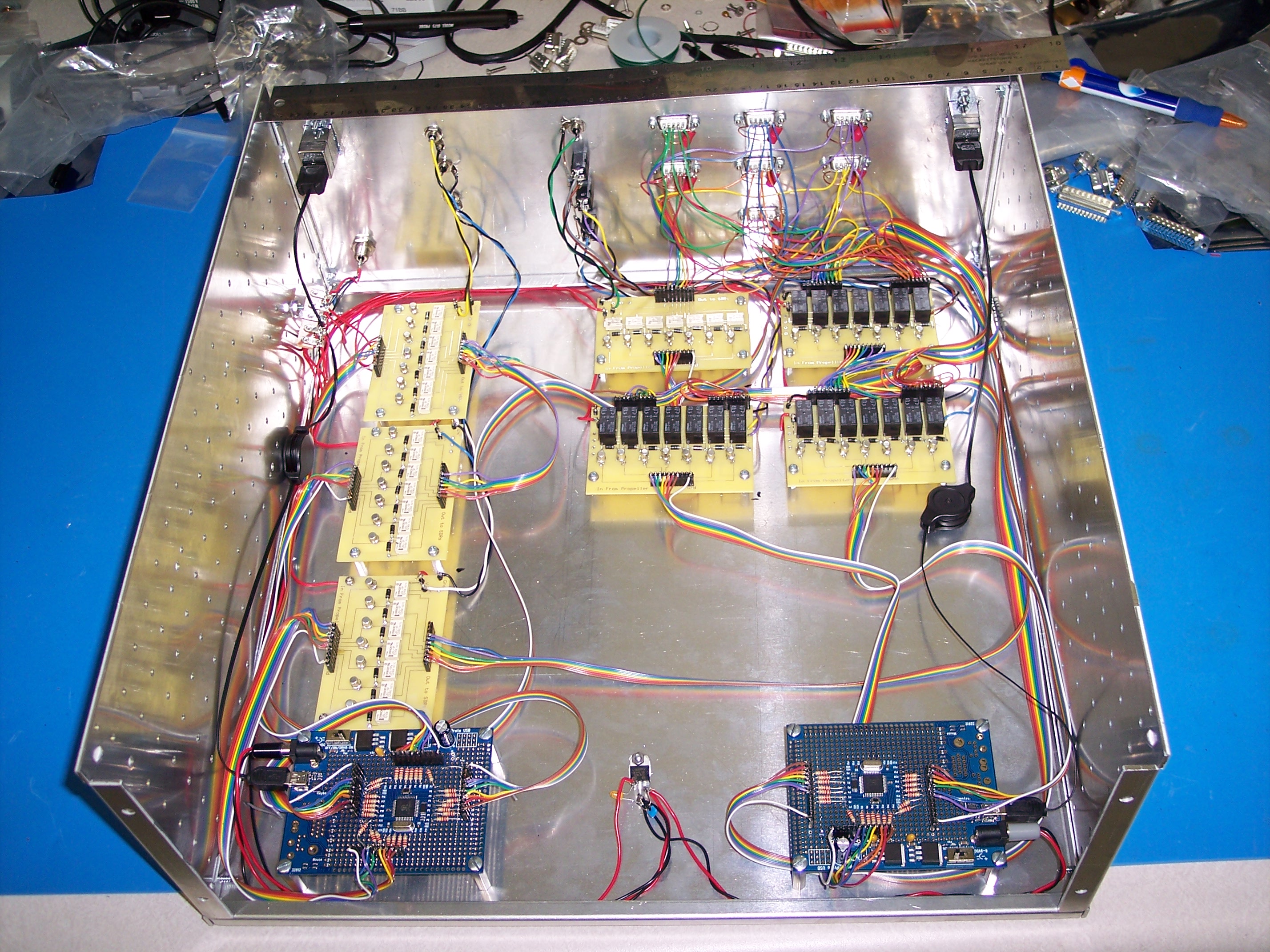
Below is a photo taken during construction of the layout of the controller
[no longer needed with the new remote-capable software, but still usable if
desired] with the 2 Parallax Propellers at the top
and the 4 RadioManager boards with small beige relays, and the 3 Audio
Controller boards with the larger black relays. The ExpressPCB PCB file for
the RadioManager boards is here.
The ExpressPCB PCB file for the Audio Controller boards is
here. The ExpressPCB schematic
file for the RadioManager boards is
here.
The ExpressPCB schematic file for the Audio Controller boards is
here.
Below is how the Controller looks when completely wired.
Below is a front view of the finished product.
Below is a view of the rear panel.
Below is a picture of the SDR controller
and five of the seven
computers with their associated HPSDR units. The sixth and seventh computers
are off-screen. This software is not intended to be used
as is by other operators, as it was designed/built to be used at my station, but
the source code is provided with the hope that it may help others in their
software building efforts. Below are links from which you can download the
source code. The reported size of the source code files will change as I
tinker with the software.
Client
~15 MB 1. The large FFT. A large FFT, used to reduce the bin
size for the spectrum display and waterfall, is essential for weak signal
work. I added large bin size to the openHPSDR version of PowerSDR and this
was eventually incorporated into the main open HPSDR PowerSDR trunk. I
have found that an FFT size of 262144 provides, for me, optimal sensitivity.
I included FFT sizes of up to 524288 in this release. The optimal size of the FFT for audio processing and graphic
signal display are quite divergent. For this reason I kept the audio FFT
size unchanged in this software, and added FFT size selection only to the
graphical display code. The architecture of the pre-existing software made
using the included SharpDSP FFT routines for this purpose difficult, and so I
first included a hand-coded FFT routine. This code is contained in
fourier.cs, which is included in source code I distributed, but is not used.
I ended up using FFTW. This is written
for C, but there is a nice wrapper for C# use named
FFTWSharp. This did not
include support for using Wisdom to optimize the FFT calculations, so I made a
simple extension to the dll to permit Wisdom use. This extension merely
consisted of adding the following lines to the code: The modified DLL is included with my source code distribution,
and the FFTWSharp source as modified by me is available
here. If the
modified DLL is included in the project bin directory and appropriately
referenced by the C# project, no additional coding is necessary to use the
extended DLL. 2. Audio. Unlike PowerSDR, the original KISS
Konsole did not provide a computer audio stream so that the user could listen to
the HPSDR hardware using the computer audio system/speakers/headphones.
Instead, one needed to obtain audio from the headphone jack of the HPSDR
hardware [Mercury/Hermes/etc.]. I added computer audio output, first using the
Naudio C# wrapper for Windows audio
functions. Naudio can be added to C# using the
Nuget Package Manager, which integrates
very nicely into Visual Studio. Ultimately I decided that the
CSCore audio package provided some
advantages over Naudio, and so the final code uses CSCore audio rather than
Naudio. The code to add audio to KISS Konsole was minimal, but it took me a bit
of trial and error to optimize it. 3. CW Sidetone. I also used CSCore to provide a CW
sidetone. In order to hear the sidetone on the at the client computer,
I use an Ethernet port to send a 1 to indicate "KeyOn" and a 0 to indicate
"KeyOff". This works for slow to medium speed CW, but is not usable for
high-speed CW. I didn't work further on this, because I believe changes to
the CW code are to be part of the next iteration of the HPSDR software and may
render all of this moot. I will review the next iteration of the HPSDR
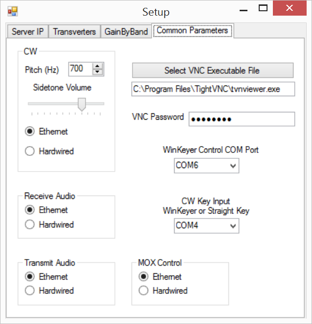
software before deciding what else I need to do here. 4. Remote Capability. The software allows operation of
the system from a remote location, using either wired or wireless ethernet
communications. A computer microphone is used for transmit audio, a CW Key
with or without WinKeyer is attached to a COM port of the computer running the
client software at the operator's location, and a footswitch is attached to the
same COM port to provide convient MOX control, although the onscreen MOX button
can also be used. Full operation of the station from 50 MHz through 24
GHz, with automatic bandswitching is possible from a remote location. I
use this software on a daily basis to operate my remote station from home. If you have any questions on the coding, or even better,
suggestions, please email me. If you hold an amateur radio license, then
you will know how to contact me in this manner. Copyright ©
1997-2015 COPYRIGHT Roger Rehr W3SZ.
All Rights Reserved
Brought
to you by the folks at W3SZ


Server
~15 MB
The code was compiled with Visual Studio 2013 and
Framework 4. A few aspects of the new coding are described below.
/// <summary>
/// W3SZ imports a wisdom plan
///
</summary>
/// <param name="plan">The plan to output</param>
[DllImport("libfftw3f-3.dll",
EntryPoint =
"fftwf_import_wisdom_from_filename",
ExactSpelling = true,
CallingConvention = CallingConvention.Cdecl)]
public static extern int
import_wisdom(string filename);
/// <summary>
/// W3SZ exports a
wisdom plan
/// </summary>
/// <param name="plan">The plan to
output</param>
[DllImport("libfftw3f-3.dll",
EntryPoint =
"fftwf_export_wisdom_to_filename",
ExactSpelling = true,
CallingConvention
= CallingConvention.Cdecl)]
public static extern int export_wisdom(string
filename);
}