Linrad Rig Control for the K3
Windows Network Version
For Use With WriteLog
Windows Network Version
For Use With WriteLog
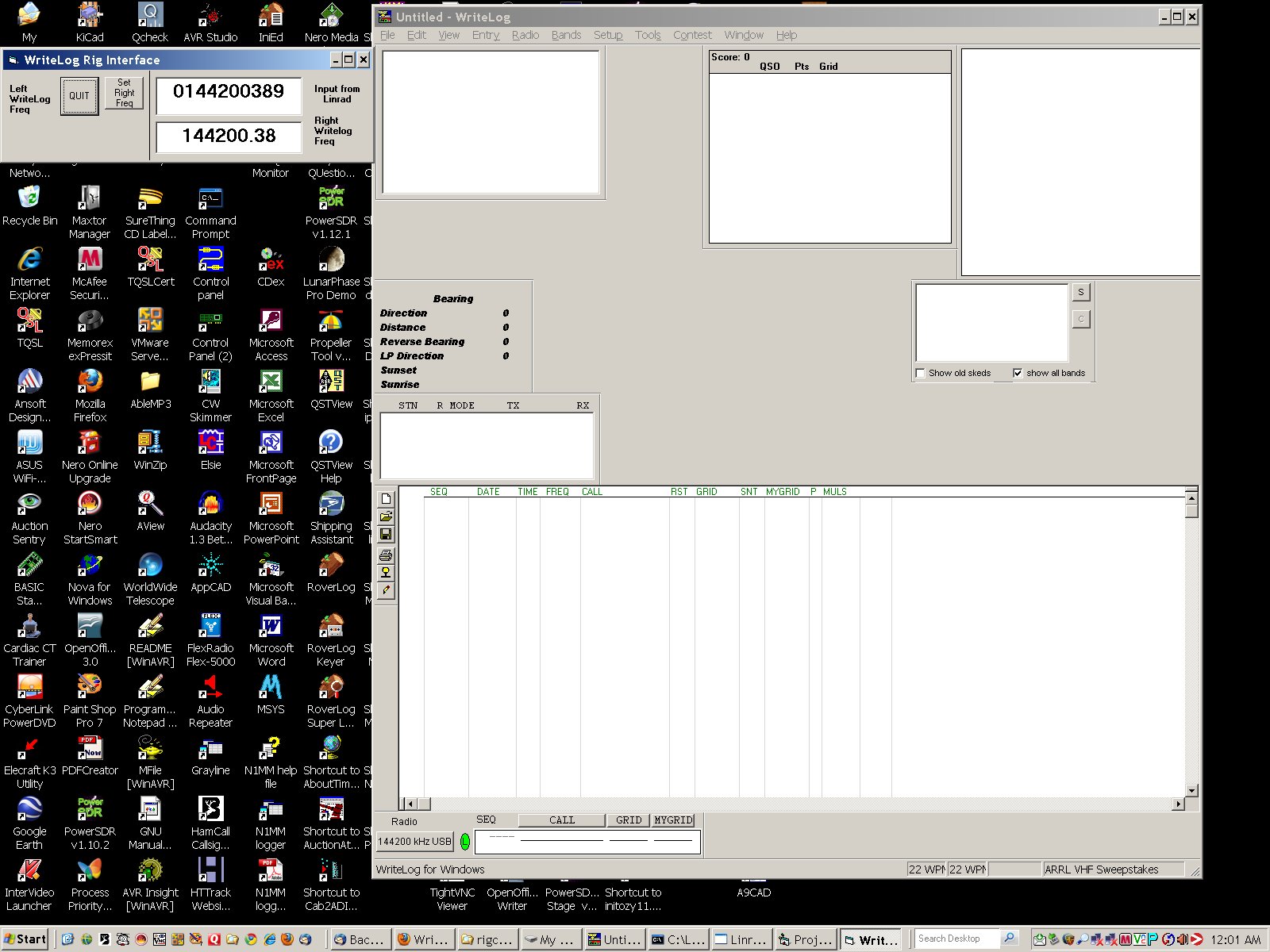
For EME use I run Linrad under Windows XP on one computer, MAP65 on a second computer also running Windows XP, and WriteLog on a third computer also running Windows XP. My Elecraft K3 is controlled by the logging program WriteLog, via a serial port on that computer.
I made a simple add-on to Linrad so that when a signal of interest is spotted on the Linrad bandscope, typing 'U' or 'Q' on the keyboard causes Linrad to send its frequency information over the network to a tcp server program on the WriteLog computer. That program tells WriteLog to tell the K3 to go to the Linrad frequency of interest, so the station can be immediately worked.
The c add-on for Linrad, wusers_hwaredrivertcp.c, is located here. To compile it into Linrad, you need to rename it to wusers_hwaredriver.c and put in in your Linrad directory.
A zip file containing the source and executables for the Visual Basic tcp server that interfaces with WriteLog is here.
These files are templates only, specific to my installation. You will need to modify them [for example, provide in the c add-on to Linrad the correct ip address of the computer that has the tcp server and WriteLog on it] to get them to work on your system.
This add-on adds a user box to the Linrad screen that looks like this:
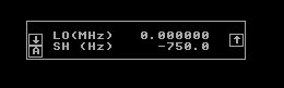
This box allows the user to set two parameters that are used to set the K3 to transmit on the proper frequency, by correcting the frequency value sent to it from Linrad for the nominal LO frequency of the transverter, and a smaller value for the offset from the nominal frequency due to parts variance, thermal drift, etc. When you run a Linrad mode [wcw, ssb, etc.] for the first time after compiling Linrad with the add-on, this box will be in the upper left corner of the screen. You need to pull it to where you want it to be. On subsequent Linrad starts it will remain where you put it. The setup information is stored in a file unique for each mode. These files are placed in the Linrad working directory, and are named aawcw_file, aassb_file, etc.
Par1, the first parameter, is used to set the approximate transverter LO in MHz. Par2 is then used to fine tune the frequency offset by entering its value directly in Hz. On the Linrad screen in the user box Par1 is the upper parameter and is labeled "LO(MHz)". If the Elecraft K3 is used as the transmitter, and if it is operating in 'transverter mode' and set to 144 MHz, then the LO would be entered as 0 [as shown]. If the K3 is not operating in transverter mode, then the LO would be entered as 116.0.
Par2 [the bottom parameter, labeled "SH(Hz)"] is the frequency correction parameter that is used to adjust for the variable frequency offset between the Linrad WSE
hardware and the K3/transverter combination that is due to parts variances, component drift,
etc. Par2 is scaled so that 1,000 equals 1 kHz. So you can just enter the offset required in Hz. Typing the letter "Q" (for "QSY")
or "U" for "User" on the Linrad computer keyboard causes the main VFO frequency
of the K3 to be set to the Linrad receive frequency minus the LO frequency plus
the offset frequency. With a Linrad receive frequency in the 144 MHz band and
par1 set to 0, the program sends a frequency instruction in the 144 MHz band to
the K3, as appropriate for the K3 when it is in transverter mode.
If you have any questions or
comments, just let me know.
Copyright 1997-2009 COPYRIGHT Roger Rehr W3SZ. All Rights Reserved