The Lin2FT Page
This is a simple add-on to Linrad to allow it to control (1) the transmit frequency of a Yaesu FT-1000 MP Mk V and (2) the frequency of the receiver local oscillators, by W3SZ. Nota Bene: This program has been replaced by a newer program which you can see at: Lin-2-1000MP.htm .
Linrad is an extraordinary weak signal receiver by SM5BSZ. It currently lacks transmit capability, and manually tuning a separate transmitter as one changes the Linrad receive frequency quickly becomes tiresome. Manually varying the receiver LO to move to new 90 KHz bandsegments is equally tiresome. This is particularly so because changing frequency within a 90 KHz band segment is so easy with Linrad; one just clicks with a mouse on the desired signal and it is centered in the receive passband. So having to zero-beat a separate transmitter or move away from the Linrad screen to change the receiver LO really slows things down. Lin2FT, a simple Visual Basic program I wrote, allows Linrad to control both the frequency of a separate transmitter, in this case a Yaesu FT-1000MP Mk V, and the frequency of the receiver local oscillators (PTS Synthesizers) from within Linrad.
Here at W3SZ I run Linrad on a 1.4 GHZ Pentium 4. This machine is pretty much dedicated to Linux and Linrad, and I have my Yaesu FT1000MP Mk V, PTS synthesizers, and other hardware hooked up to a separate computer that is running Windows 98. The FT1000 is controlled via a Comtrol RocketPort Serial Port, and the PTS synthesizers are controlled via a National Instruments GPIB Interface card. Both of these are devices with Windows drivers.
This arrangement gives me an easy way to control both the transmit frequency of the FT1000 and the receiver local oscillators from Linrad. I just have Linrad send its receive frequency and the necessary local oscillator frequency information to the computer controlling the FT1000MP and the PTS synthesizers, and then that computer sends the desired information to the hardware. All of my computers are networked together, but because the network occasionally-to-rarely goes down I elected to use a vacant serial port on the Linux machine to communicate with one of the RocketPort serial ports on the Windows computer. The Windows Visual Basic program Lin2FT receives the data from the Linux machine running Linrad, processes that data to put it in the form that the FT1000MP and PTS synthesizers need, adds any offset needed to adjust for any frequency discrepancies between the Linrad receiver and the FT1000MP/transverter combination, and sends the frequency control information to the FT1000MP and the PTS synthesizers. Doppler shift is currently handled by adjusting the Tx offset on the FT1000MP, although this could easily be added in software if desired. I likely will add Azimuth and Elevation rotor control shortly. The program already has a subroutine reserved for this, which will be completed once I see the form of the Az and El data from Linrad.
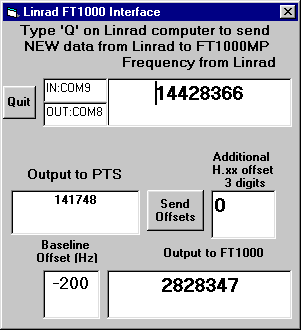
The Windows Display for the program is shown above. Near the top left is a radio button marked 'Quit". Clicking on this will exit the Visual Basic Program. To the right of this is an information box that indicates that the program receives data in from Linrad on COM9, and sends data out to the FT1000MP on COM8. This is there just because I tend to forget which of the many com ports I have are assigned to which pieces of hardware. To the right of that box is an information box that shows the current receive frequency for the Linrad program (144.28366 MHz), as received from Linrad via the serial port. On the line below, on the left, is the local oscillator frequency information that is sent to the PTS synthesizers. Only six significant digits are sent to the PTS synthesizers, as only coarse local oscillator tuning is necessary since the Linrad program itself does the fine tuning. The value 141748 represents a local oscillator frequency of 141.748 MHz, which corresponds (with a 2.5 MHZ IF frequency) to a receive center frequency of 144.248, and a waterfall display range of 144.200 to 144.290 MHz. This frequency is derived from the information that is entered in the small receive-hardware window on the Linrad receiver screen. At the start of Linrad, or each time the data in this Linrad window is changed, Linrad sends the new LO frequency to the PTS synthesizers via this Visual Basic Program. So Linrad can be used on any frequency covered by the PTS synthesizers with just a click of the mouse. To the right of this local oscillator frequency display is a radio button marked "Send Offsets". This is used to correct for any variable frequency discrepancy between Linrad and the transmitter/transverter, without changing the Linrad receive frequency used by the Visual Basic program. One would use this if one discovered that the default offset did not place the FT1000MP on the correct frequency. Just to the right of this button there is a box with which to enter the variable frequency offset in KHz and tenths and hundredths of a KHz, entered as 3 digits 'xyz'representing x.yz KHz, optionally preceded by a plus or minus sign. The Visual Basic program has as a default a -200 Hz offset because the transverter here is 200 Hz high in frequency. Any offset entered in the text box just discussed will add or subtract additionally from the frequency sent to the FT1000MP. So if an additional offset of 200 Hz '020' is entered, the total offset would be zero (-200 + 200). The additional offset is always added to the Linrad receive frequency when that information is sent from the Linrad computer to the Windows computer, and the appropriate frequency data plus offsets is then sent to the FT1000. These actions are triggered by typing the letter "Q" (for "QSY") on the Linrad computer keyboard. Additionally, as noted above, the offset can be changed using Lin2FT without getting new frequency information from Linrad and the newly adjusted frequency sent from the Windows computer to the FT1000MP by clicking the "Send Offsets" button on the Display Window for the Visual Basic program Lin2FT. When this is done the receive frequency information from Linrad will not be updated. This allows the receive frequency to vary if the other station drifts without causing the transmitter to waltz around the band as well. The bottom line of the display shows the default offset (-200Hz), and the actual frequency instruction sent to the FT1000MP. Note that for a receive frequency in the 144 MHz band the program sends a frequency instruction in the 28 MHz band to the FT1000MP, as appropriate for the transverter setup here.
Minimal modifications to Linrad are necessary to make all of this work. Leif has modified Linrad00-51 and later so that the user program for changing the FT1000MP's frequency will be invoked if "Q" is typed, as noted above, and the code to change the LO frequency will be invoked whenever the information in the receive hardware frequency box is changed on the Linrad screen. The Linrad00-51 and later code will compile and run user-defined code that is placed in a file called users_hwaredriver.c. You can create this driver by copying users.c to users_hwaredriver.c and modifying this code as necessary.
Once that is done, just do ./clean, ./configure, and make and run linrad. No errors should result (I get none here on a Linrad00-51). In the future if you make changes to users_hwaredriver.c you can then skip the ./clean and ./configure commands, and just do make.
I have put the entire 'users_hwaredriver.c' file here, just copy it into
your Linrad directory, type ./clean, ./configure and make once you
have Linrad00-51 or later.
The Visual Basic code is a bit longer, but still not difficult. I've put the source code in this file lin2ft.txt. This will give you an example of what to do to get things working for your particular setup. Modifications are of course necessary for different hardware. The Visual Basic code is not pretty, but it works fine here. Some day I might pretty up the code. It could happen.
Copyright 1997-2007 COPYRIGHT Roger Rehr W3SZ. All Rights Reserved
Brought to you by the folks at W3SZ