RTL-SDR WITH LINRAD UNDER LINUX.
(July 3 2012)

The rtlsdr USB dongle.

Marketed as DVB-T LAPTOP DIGITAL TV Tuner USB Stick HDTV Realtek RTL2832U / E4000 SDR or similar one can find these surprisingly good receivers on the Internet for perhaps USD 20. They may look like the ones in figure 1.


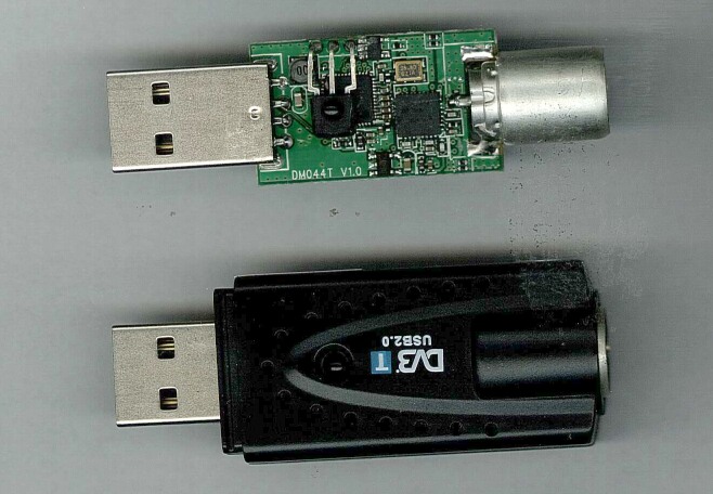
Fig. 1. USB dongles for digital TV and FM radio.

For more info look here: http://sdr.osmocom.org/trac/wiki/rtl-sdr

This page contains measured data from the two units shown in figure 1. They are ezcap USB 2.0 DVB-T/DAB/FM dongles vith VID = 0x0bda and PID = 0x2838.

The performance demonstrated here is with modified software for Linrad under Linux. Dongles with other tuners than the E4000 are not (yet?) supported in Linrad under Linux.

Performance under Windows with the original software from osmocom june 2012.

The noise figure is 19 dB at 144 MHz. This means that MDS (the noise floor in 500 Hz bandwidth) is at -128 dBm. When another signal in the passband reaches -69 dBm all signals are compressed by 3 dB. The reason is an AGC inside the RTL2832 chip.

The dynamic range measured as the separation between MDS and the point of 3 dB compression is only 59 dB. For this reason rtlsdr is often classified as a toy rather than as a radio. Even so, the rtlsdr toy has became popular.

Performance in linrad-03.40 under Linux.

In linrad there is a gain control. With the rtlsdr USB stick it goes from -30 to +18 dB in steps of nominally 3 dB. The real gain steps are between 0 and 5 dB and the gain is changed at six different points in the signal path.

The noise figure is of course lowest at maximum gain and as usual that comes with a loss of dynamic range. Table 1 shows Noise figures and the point of saturation for the two identical dongles in my possession.


 Gain          Dongle #1                          Dongle #2
setting  NF    MDS    Sat.   Range          NF    MDS   Sat.   Range
  (dB)  (dB)  (dBm)  (dBm)   (dB)          (dB)  (dBm)  (dBm)  (dB)
   18   7.0  -140.0  -66.2   73.8          6.7  -140.3  -65.0  75.3
   15   7.4  -139.6  -63.2   76.4          7.1  -139.9  -62.8  77.1
   12   8.3  -138.7  -60.0   78.7          8.0  -139.0  -59.9  79.1
    9   9.9  -137.1  -56.8   80.3          9.8  -137.2  -57.2  80.0
    6  12.2  -134.8  -54.5   80.3         12.0  -135.0  -55.1  79.9
    3  14.5  -132.5  -51.6   80.9         14.4  -132.6  -52.0  80.6
    0  ~19           -47.2                              -47.5
   -3  ~19           -47.2                              -47.5
   -6  ~24           -42.2                              -42.6
   -9  ~26           -40.4                              -41.0
  -12  ~30           -36.7                              -37.3
  -15                -35.4                              -36.2
  -18                -31.4                              -32.2
  -21                -30.1                              -30.8
  -24                -27.0                              -27.6
  -27                -24.5                              -25.2
  -30                -19.6                              -20.0
Table 1. Noise floor, saturation and dynamic range of two rtlsdr USB dongles at 144 MHz for some different gain settings in Linrad.


The noise floors in table 1 were measured with a noise figure meter. At gain settings from 0 to -30 the noise figure will about 17 to 47 dB with a range of about 80 dB from MDS to saturation. In Linrad-03.40 there is no AGC in the dongle.

Quantization noise and distortion.

The data delivered from the rtlsdr is only 8 bit. An ideal 8-bit A/D converter should have a SNR of 50 dB The bandwidth delivered by the rtlsdr is 2 MHz while we measure MDS in a bandwidth of 500 Hz. The bandwidth factor is 4000 and that provides a gain of 36 dB so the measured performance is 6 dB below the theoretical limit.

If the peak to peak level of the input to the A/D converter were well below one bit, the output could be zero (all data points have the same value) or it could be a random sequence of two values. If the probability of both values were equal, the RMS noise would be 0.5 bit even if the real noise at the input were very much smaller.

Figure 2 shows the A/D output for a -74dBm signal that is close to the center frequency. Gain is set to -30 dB. It is quite clear that the signal is a stepped function and not a sinewave and that is because there is no other signal present. At some points in time the noise is zero and at other points in time the noise is 0.5 bit RMS.


Fig. 2. The A/D output from a dongle. The input is -74 dBm with a signal near the center frequency. I and Q is green and magenta respectively. When both I and Q have the same value the pixel is white.


The spectrum of the signal in figure 2 is shown in figure 3. The DC component is visible at 144.0 in the baseband graph. That is the frequency to which the dongle is set. The -74 dBm signal is at 143.99903 and it comes from the E4000 tuner to the RTL chip as an pair of audio signals just below 1 kHz. The overtones are pretty strong. They are only 26 dB below the main signal and correspond to false signals at -100 dBm. These spurs are 80 dB below the point of saturation which is at -20 dBm when gain is set to -30 dB.


Fig. 3. The spectrum of the signal shown in figure 2. See text.


The quantization spurs do not increase when the level of the signal increases and they disappear when noise or other signals are present. (Dithering.)

When the level at the A/D input is low, the conversion from analog to digital produces some gain. Consider the case with a sinewave of amplitude 0.1 bit and with a noise level much lower than that. The output would be a square-wave of amplitude 1 bit. This kind of phenomenon exists in the donle. To demonstrate this effect, a signal at the MDS level, -103 dBm was sent into the dongle on 144.500 MHz. The center frequency was set to 144.000 MHz and gain to -30. The signal amplitude is much below the noise, 29 dB weaker than the signal shown in figure 2.

A variable signal on 143.8 MHz was also sent into the dongle. Table 2 shows how the amplitude and S/N of the weak signal at 144.500 varies with the level of the signal at 143.8 MHz.


143.8             144.5      
Level        Level    S/N
(dBm)        (dB)     (dB)
 off         1.5      0.7
-82          1.3      0.5
-79          1.3      0.5
-76          1.1      0.3
-73          0.7      0.2
-70         -0.1     -0.1
-67         -0.5     -0.2
-64         -0.5     -0.2
-61          0.3     -0.2
-58         -0.5     -0.1
-55          0.5      0.2
-52          0.3      0.2
-49          0.0     -0.1
-46          0.2     -0.1
-43          0.0      0.0
-40          0.0      0.0
-37          0.0      0.0
-34          0.0      0.0
-31          0.0      0.0
-28          0.0      0.0
-25          0.0      0.0
-22          0.0      0.0  
Table 2. At really low levels the A/D converter may produce gain or attenuation of a weak signal as well as the noise floor depending on the level of a signal on another frequency. In real life this is insignificant because the gain should always be set high enough for the strongest signal to be well above the noise floor.


Table 2 shows gain as well as improved S/N due to the step-function of the A/D converter. It is an artifact of accademic interest only. The table also shows that the noise floor does not increase when a signal 81 dB above the noise is present at an offset of 700 kHz. Reciprocal mixing is not present, the phase noise of the local oscillator is well below -108 dBc/Hz on 144 MHz.

Gain compression.

Signals within the passband saturate the A/D converter before they cause gain compression in the E4000 tuner. Signals at greater frequency offsets can be stronger because there is a filter in the E4000 tuner that reduces their level at the RTL2832 input. (Anti alias filters.)

Table 3 shows the level required for 3 dB gain compression at offsets of 1, 2 and 10 MHz. The level depends of course of the gain setting. There are many gain controls inside the E4000 tuner and the table shows how the settings implemented in Linrad-03.40 affect the gain compression characteristics.


         Interference level for 3 dB compression
  Gain          Offset    Offset    Offset    
setting         1 MHz     2 MHz     10 MHz
  (dB)          (dBm)     (dBm)      (dBm)
   18            -54 S     -43       -30 
   15            -52 S     -43       -30
   12            -49 S     -41       -30
    9            -49 S     -39       -29
    6            -44 S     -36       -26
    3            -41 S     -35       -26
    0            -36 S     -31       -20
   -3            -36 S     -31       -20
   -6            -32 S     -26       -16
   -9            -30 S     -24       -16
  -12            -26 S     -21       -13
  -15            -25 S     -19       -13
  -18            -21 S     -16        -8
  -21            -19 S     -16        -8
  -24            -16       -13        -8
  -27            -15       -12        -7
  -30             -9        -9        -6
Table 3. The signal level that causes 3 dB compression. In some cases the A/D saturates before compression happens. Those are marked with S in the table.


Audio harmonics.

In zero IF systems audio harmonics can be a problem. Figure 4 shows a near saturating signal that is stepped from 142.1 to 144.250 in steps of 30 kHz.


Fig. 4. A near saturating signal stepped in frequency.


The audio harmonics are suppressed by a bit more than 60 dB and they decrease rapidly as the signal level decreases. It is clear from figure 4 that aliasing can be a problem. A narrow filter at the input of the dongle may be required.

LO spurs.

There is an internal spur at 144.0 MHz as can be seen in figure 4. If the LO is set to 144.000 this spur disappears into the center DC peak. The LO will however be affected and strong signals show sidebands as can be seen in figure 5.


Fig. 5. With the LO at 144.000 there is close range modulation on the LO.


When the LO is shifted by a small amount the signal splits into three components. See figure 6. The signal itself and two spurs. When the LO frequency is shifted by 10 kHz the spurs shift by 240 kHz so they somehow relate to the 24th overtone of the LO.


Fig. 6. With the LO at 144.010 one can see that a significant part of the close range modulation on the LO belongs to spurs that move 24 times faster than the LO.


Reciprocal mixing.

The Txtest mode in Linrad can be used to evaluate the noise floor near a strong signal. The red track is RMS power in a bandwidth of 2.4 kHz.


Fig. 7. A strong signal in txtest mode.


Table 4 shows the noise floor at different distances from the carrier as evaluated from figure 7.


 Offset     Noise floor          
 (kHz)       (dBc/Hz)
   10           96
   20           99
   50          101      
  100          106
  200          108
Table 4. Reciprocal mixing.


How to install the rtl-sdr library for Linrad under Linux.

The performance demonstrated on this page is obtained with a slightly modified version of the rtl-sdr library in July 2012.

To install the modified rtlsdr library for Linrad, use the sequence of commands that is displayed when the configure script is run like this: ./configure --with-help Use the mouse to copy and paste the commands into the command line when logged as root. Do not forget to run configure again before running make!!

The modified code for rtlsdr disables the AGC in the RTL2832 chip and uses the different gain controls in a way that optimizes the noise figure at high gain settings and the dynamic range at low gain settings.