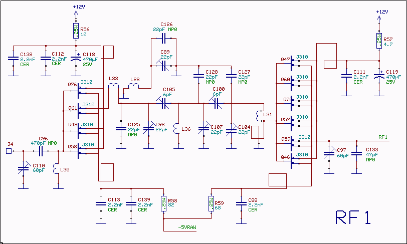
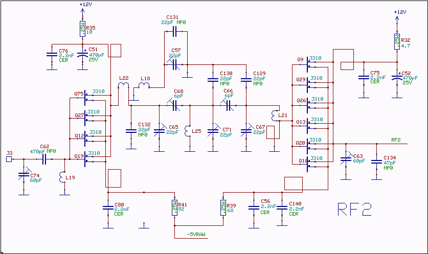
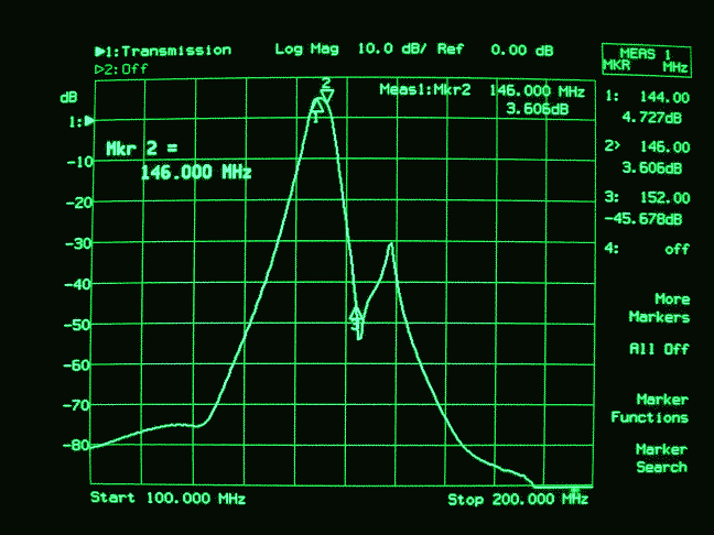
The RF amplifierThe RF amplifiers use noiseless feedback through the drain-gate capacitance with an inductor in the source lead to provide the necessary 90 degree phase shift between gate voltage and channel current.The first RF amplifier gives about 4dB gain with a noise figure of about 2dB. The filter attenuates by about 3dB, then the second RF amplifier with twice as many transistors gives another 4dB gain for a total gain of about 5dB. The schematic diagram is shown in figures 1 and 2 and the frequency response with the output matched to 50 ohms is shown in fig. 3. The third order intercept point at the input is +35dBm, the output IP3 is +40 dBm which is required to overcome the losses of the load resistors at the mixer input and make sure that the IP3 of the mixer itself dominates the IP3 of the entire RX144 unit.
|