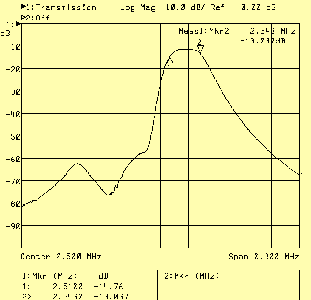
Fig 1. Frequency response for the six Amidon toroids of a RX2500 configured for a transmit filter to use with a Delta44.
Problems.The first step, going from the baseband I and Q to 2.5 MHz has several problems. When a 96kHz D/A converter giving output at the frequency F is used to produce the desired frequency 2.5MHz + F at the output of a mixer with a 2.5 MHz LO, the following frequencies may appear:2.5MHz (LO leakage) 2.5MHz - F (mirror) 2.5MHz + 96kHz (sampling clock) 2.5MHz - 96 kHz (sampling clock) 2.5MHz + 48kHz - F (alias) 2.5MHz -48kHz + F (alias) 2.5MHz + 2*F (2nd harmonic) 2.5MHz - 2*F (2nd harmonic) 2.5MHz + 3*F (3rd harmonic) 2.5MHz - 3*F (3rd harmonic) 2.5MHz + 4*F (4th harmonic) 2.5MHz - 4*F (4th harmonic) The harmonic level is about 100 dB below the main signal in the baseband. The Delta 44 does not really put out its samples at 96 kHz so there is no corresponding spur - or at least it is very weak. There is a digital anti-alias filter in front of the D/A output which runs much faster than 96 kHz. When F is near 48 kHz, the alias signal is very strong but it falls rapidly like this: F Alias level (kHz) (dB) 46 -19 45.5 -25 45 -32 44.5 -40 44 -52 43.5 -72The peak amplitude of the signal and the alias together is constant and both approach -6 dB at 48 kHz. A tx converter from baseband to 2.5 MHz could use anti-alias filters in the baseband to allow frequencies between about 42 and 45 kHz in the same way as in RX2500. Such a solution would degrade the balance between I and Q. Without, or with very simple filters in the baseband, it seems reasonable to go for an upper frequency limit of 43 kHz. The frequency stepping of the 2.5 MHz to 10.7 MHz converter is 25 kHz which means that the lowest frequency limit has to be 10 kHz if a maximum bandwidth of 8 kHz should be allowed at any frequency. This looks like a crystal filter, but even that would not quite allow a spur-free transmitter since the overtone spurs would pass a filter like this. Performance of TX2500, a modified RX2500It seems reasonable to allow an image spur as well as some 2.5 MHz LO leakage by using a filter composed from the components of a RX2500. Figure 1 shows the frequency response that can be obtained and figure 2 shows the spectrum at 2.5 MHz as seen with another computer using an RX2500 and a modified Delta 44.The image spur is suppressed by about 70 dB. The 2.5 MHz LO and the overtone spurs are just a little better. The input is an audio tone at 1.75 kHz from a tone generator into the microphone input. Linrad is transmitting in SSB mode. The noise floor within the SSB bandwidth is about 70 dB above the noise floor between the spurs. The signal is keyed and during key-up one can see that the noise is very similar on both sides of the center. During key-up the noise floor is about 112 dB below the signal in a bandwidth of 2.4 kHz which converts to about -146 dBc/Hz. During key-down the noise on the high frequency side is lifted by about 1 dB which means that the transmitter has a very low noise floor. As compared to conventional amateur equipment, the TX2500 and Delta 44 combination in this first version has spurs that are about 20 dB above normal. This is highly undesireable for real operation on the ham bands, but for studying the noise floor, modulation, T/R switching and other aspects of the rest of the transmit chain it does not matter so the TX2500 and Delta 44 combination will be the starting point for now. A 192 kHz soundcard would be a much better choice for the transmit side. It could operate from 55 to 88 kHz with the worst case overtone spur 22 kHz outside the filter and with the LO leakage 55 kHz away. The worst case image spur, 110 kHz outside the filter would not be a problem and the worst case alias spur 16 kHz above 88 kHz should already be below -100 dB due to the digital anti-alias filter inside the soundcard so it should be possible to attenuate it a bit more. |

Fig 1. Frequency response for the six Amidon toroids of a RX2500 configured for a transmit filter to use with a Delta44. |
|
|

Fig 2. The output of TX2500 as seen by a RX2500. |
Practical details.The first version of the TX2500 is just a temporary solution to allow software development and development of the rest of the transmit chain. For this reason no practical details are made available here.To SM 5 BSZ Main Page |